




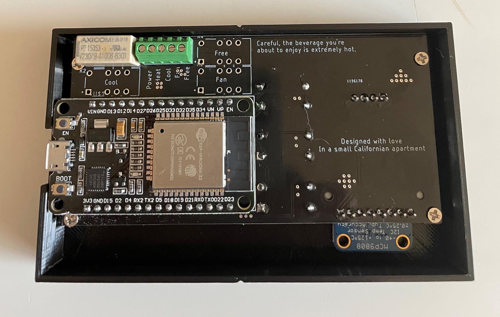
To make a motherboard, you must follow a complex industrial manufacturing process that transforms raw materials like fiberglass and copper into a highly engineered printed circuit board (PCB), then assembles hundreds of electronic components onto it using automated machinery. This is not a DIY project; understanding how to make a motherboard reveals the precision required to create the central hub that connects your CPU, RAM, storage, and peripherals.
What a motherboard is and how to make one
A motherboard, also known as a mainboard or system board, is the central printed circuit board (PCB) that forms the backbone of any computer system. It acts as the primary platform where all critical hardware components connect and communicate, including the CPU, RAM, storage devices, and expansion cards. Key components on a motherboard include the CPU socket, which holds the processor; the chipset, which manages data flow between the CPU and connected devices like USB, storage, and PCIe slots; RAM slots for system memory; power connectors and the Voltage Regulator Module (VRM) for stable power distribution; expansion slots like PCIe for adding graphics cards; storage connectors such as SATA and M.2; the BIOS or UEFI firmware chip that stores startup instructions; the CMOS battery that powers BIOS settings; and rear I/O ports for peripherals. Before installing the board, you can power up PSU without motherboard to verify your power supply works. Motherboards come in standardized form factors, such as ATX, MicroATX, and Mini-ITX, which define physical dimensions, mounting hole positions, and connector configurations, dictating the number of expansion slots and typical use cases like desktop or compact PCs.
How a motherboard is made: from raw materials to PCB
The process of making a motherboard begins with creating the PCB itself. The foundation is a sheet of fiberglass fabric impregnated with epoxy resin, known as a "prepreg." Multiple prepreg sheets are stacked to a designated thickness and sandwiched between layers of copper foil. Copper is chosen for its excellent electrical current and heat conductivity. This stack is then laminated under heat and pressure, bonding the materials into a stiff, solid board. To create the circuit patterns, a photosensitive coating called photoresist is applied to the copper layers. A transparent artwork showing the design for tracks and pads is placed over the laminate, and the board is exposed to ultraviolet light. The board is then dipped in a chemical solution; copper underneath the design remains intact, while residual copper is etched away through a high-pressure spraying process, creating a "core." These inner copper layers are imaged, etched, inspected, and aligned with additional prepreg and copper foil before final lamination. Motherboards feature multiple copper layers to support high-speed signaling, using critical materials like FR4 (fiberglass and epoxy resin) or High-Tg FR4, which offers better thermal stress resistance for high-power boards.
Drilling, plating, and finishing the bare board
Once the laminated PCB is formed, holes are drilled for mounting, through-hole components, and vias that create electrical connections between copper layers. Mechanical or laser drilling creates through-holes and microvias with high precision. After drilling, the hole walls are made conductive through a desmear process followed by copper plating, which coats the walls with copper. This is often followed by a tin layer to prevent copper from tarnishing and to facilitate soldering. A solder mask is then applied to protect the circuit board from short circuits and soldering errors. Finally, the board is silkscreened to identify where parts should go, a process called component mapping and solder masking.
Surface mount assembly: placing the tiny components
The process of transforming a bare PCB into a functional motherboard is known as Printed Circuit Board Assembly (PCBA). Surface Mount Technology (SMT) is the primary assembly method, allowing for automated production, faster assembly, and smaller, more densely packed components. The SMT process begins with applying solder paste to the PCB pads using a stencil. Then, high-speed "pick-and-place" machines accurately position surface-mount devices (SMDs) onto the paste. After component placement, the board goes through a reflow oven, which melts the solder paste at controlled temperatures to form permanent electrical and mechanical connections, followed by rapid cooling. Typical components assembled via SMT include chipsets, BIOS ROM chips, and smaller passive components like resistors and capacitors.
Through-hole assembly and wave soldering
Larger components that require sturdier physical bonds, such as PCIe slots, CPU sockets, RAM slots, and power connectors, are often inserted by hand. These through-hole components are then secured using wave soldering, a process that provides a strong mechanical and electrical connection. The board passes over a wave of molten solder, which flows into the through-holes and bonds the component leads to the PCB. This method is essential for components that experience physical stress from repeated insertion and removal of cables or expansion cards.
Inspection, testing, and quality standards
Multiple inspection stages are integrated throughout the assembly line to ensure quality. Automated Optical Inspection (AOI) checks for correct solder paste application and component placement. Boards then undergo rigorous electrical testing, including in-circuit testing (ICT) and functional testing, to ensure all pathways work correctly and are free of shorts. Motherboard manufacturing adheres to international quality standards such as UL 796, IEC 61249-2-41, and IPC-A-600H-2010, which cover safety, materials, and inspection criteria.
Where motherboards are manufactured
Motherboard production occurs in large, automated factories, predominantly in regions like Taiwan and mainland China, with some operations in the USA and Japan. These facilities operate at massive scale, utilizing high-speed pick-and-place machines, reflow ovens, and wave soldering lines to produce thousands of boards per day. The concentration of manufacturing in these regions is driven by the availability of specialized supply chains, skilled labor, and advanced production equipment capable of handling the complex multi-layer PCBs and precise component placement required for modern motherboards.