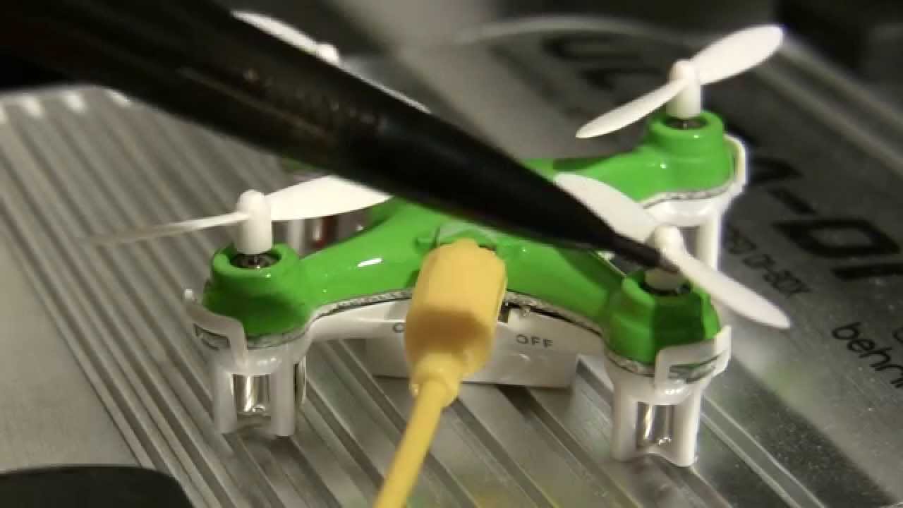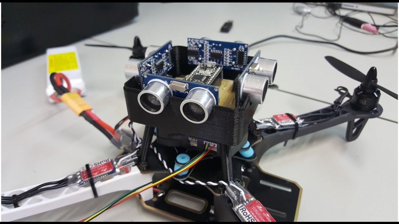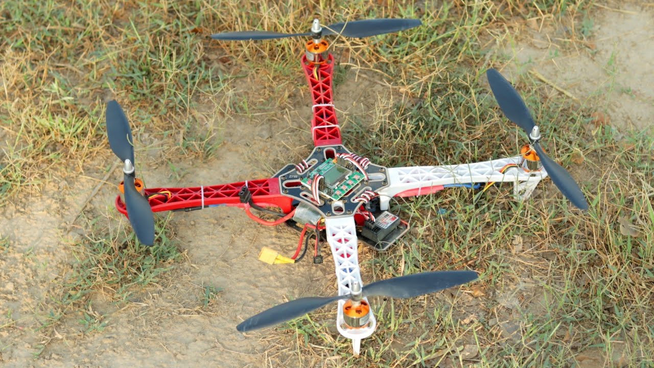





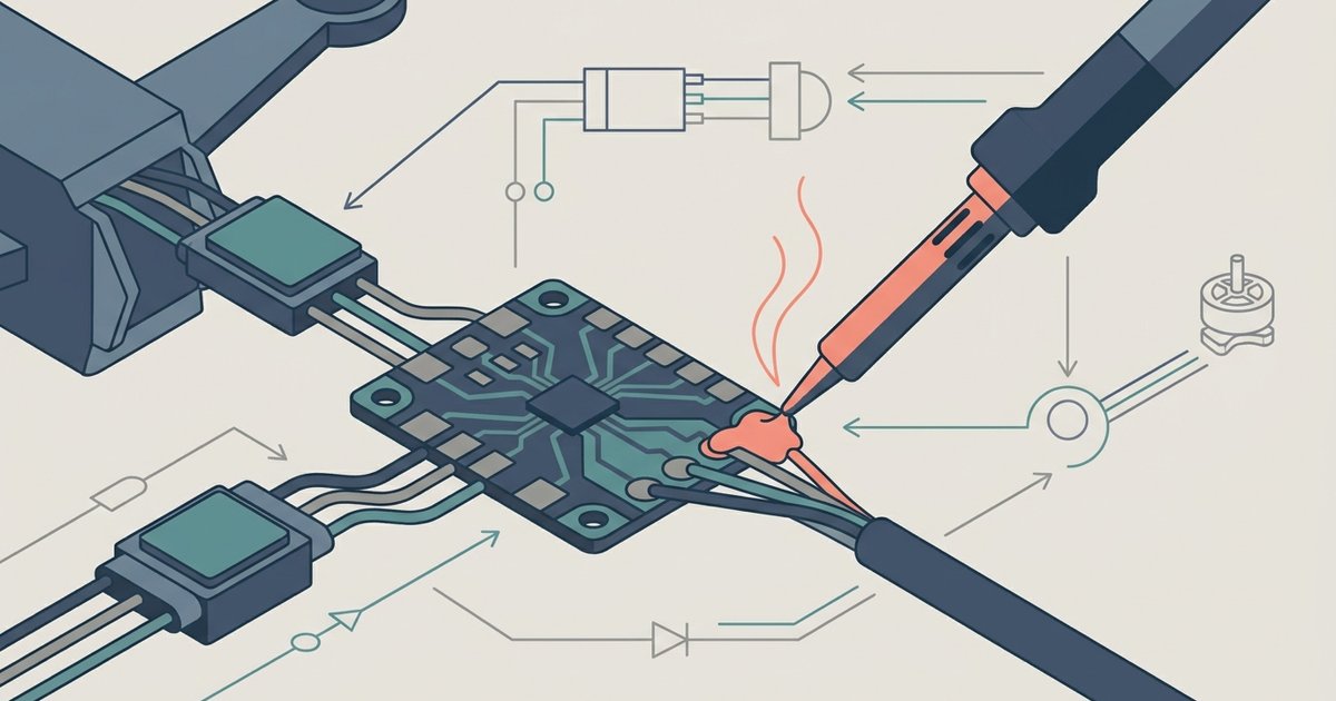
Pre-tin both the ESC power pads and wire ends, then heat the joint from one side while feeding solder from the opposite side until it flows into a shiny volcano shape. Always use a temperature-controlled iron at 350-450°C for ESC and large power pads (300-350°C for small signal pads), and keep the exposed wire length short enough that no strands can bridge to adjacent pads.
Pre-tinning for solder drone Esc pads
Stranded wire must be tinned before touching the board. Strip a short length of insulation, no more than necessary, twist the strands lightly, then apply flux to the copper. Touch the iron tip to the wire and feed solder into the strands until each filament is coated and the wire becomes stiff. For the PDB pads, clean them with isopropyl alcohol, apply flux paste, then melt a small dome of solder onto each pad. If you skip this step, the cold wire wicks heat away from the joint, the solder fails to flow into the strands, and the pad lifts under tension. A properly tinned pad looks like a silver mound; a dry joint looks grainy and dull. This technique eliminates cold joints and pad delamination, and when you later build a drone with Arduino, the same method applies to all high-current solder connections on the flight controller and power distribution board. Once your build is flight-ready, you might even order walmart drone delivery to celebrate with a contact-free package drop.
The physical joint technique
Place the tinned wire end squarely on the tinned pad. Hold the iron tip flat against one side of the junction, not on top of the wire. Wait two seconds for both metals to reach temperature, then touch the solder wire to the opposite side of the joint. If the temperature is correct, the solder instantly wicks into the gap and forms a concave fillet. Remove the iron after the solder flows, typically three seconds total. A good joint is shiny, smooth, and covers the entire pad without spilling over the edge. A cold joint looks frosty or has a crater; an overheated joint turns brown or black and loses mechanical strength.
Avoiding the most common short circuit
The deadliest error is exposed wire bridging the positive and negative pads. Strip only as much insulation as needed, never more than necessary. After tinning, trim any stray strands that stick out beyond the solder coating. When you place the wire, ensure the exposed metal contacts only its intended pad. After soldering each joint, inspect with a bright light and a magnifier: no solder balls, no filament tails, no concave meniscus crossing the gap between pads. Use a multimeter in continuity mode between the two power rails before connecting the battery. A beep means a dead short that will instantly destroy the ESC and battery.
Wire routing and strain relief
Route each ESC power wire directly to its pad without loops that can snag on a propeller. Bundle all three wires together with a zip tie close to the solder joint to prevent tugging on the pad. For a clean build, slide braided sleeving over the wire bundle before soldering, then heat-shrink the sleeving ends. Secure the main battery leads to the frame arm with a second zip tie so the PDB bears no mechanical load. Leave enough slack between the zip tie and the solder joint so vibration does not crack the connection. Verify that no wire touches the carbon fiber frame, carbon is conductive and will short the circuit if the insulation wears through. For more on the full journey of buying, building and flying drones, explore the broader topic of Drones: Buying, Building and Flying.