Introduction
Welcome to this tutorial on how to connect a power supply unit to a breadboard. If you are new to electronics or prototyping, this guide will provide you with all the essential information you need to get started with powering your projects using a breadboard.
Breadboards are a crucial tool for electronics enthusiasts, makers, and hobbyists to build and test circuits without the need for soldering. They offer a convenient platform for connecting components such as resistors, capacitors, LEDs, and integrated circuits (ICs) to create functional electronic prototypes. However, to power these circuits, you will need a reliable power supply unit.
A power supply unit, often abbreviated as PSU, is a device that provides electrical energy to electronic devices. It converts the input voltage into a stable and regulated output voltage to power the various components in a circuit. Depending on the project’s requirements, different types of power supply units can be used, such as battery packs, AC-DC adapters, or voltage regulators.
In this tutorial, we will guide you through the process of connecting a power supply unit to a breadboard. We will cover the necessary tools and components, the step-by-step procedure, and some general precautions to ensure a safe and successful connection. By the end of this guide, you will have the knowledge and confidence to power your electronic projects efficiently and effectively.
Why Use a Power Supply Unit?
Using a power supply unit to power your breadboard circuits offers several advantages over other power sources. Let’s explore some of the key reasons why using a power supply unit is an excellent choice for your electronic projects.
1. Stability: One of the main advantages of using a power supply unit is the stability it provides. Unlike batteries, which can experience voltage drops as they discharge, a power supply unit delivers a constant and regulated voltage. This stability ensures that your circuits receive a consistent power supply, reducing the risk of unexpected behavior or damage to components.
2. Voltage Control: Most power supply units have adjustable voltage settings, allowing you to select the desired output voltage for your circuits. This feature is particularly useful when working with sensitive components that require specific voltage levels. You can easily fine-tune the voltage to match the requirements of your circuit, ensuring optimal performance and longevity.
3. Higher Current Capacity: Compared to batteries, which have limited current output, power supply units typically offer higher current capacity. This is particularly beneficial when working with circuits that require a significant amount of current to drive motors, high-power LEDs, or other power-hungry components. With a power supply unit, you can confidently power such circuits without worrying about draining batteries or risking voltage drops.
4. Cost-Effective solution: While the initial investment in a power supply unit may seem higher compared to disposable batteries, it provides a cost-effective solution in the long run. Batteries need regular replacements, causing recurring expenses. A power supply unit eliminates the need for constantly purchasing new batteries, saving you money over time.
5. Eco-Friendly: Power supply units are eco-friendly alternatives to disposable batteries. Batteries not only contribute to environmental waste but can also leak harmful chemicals if not disposed of properly. By using a power supply unit, you reduce waste and minimize your impact on the environment while enjoying the convenience of a reliable power source.
In summary, a power supply unit offers stability, voltage control, higher current capacity, cost-effectiveness, and eco-friendliness. These benefits make it an ideal choice for powering your breadboard circuits. By utilizing a power supply unit, you can ensure consistent and reliable power to your projects, allowing you to focus on exploring and creating without the limitations of battery power.
Overview of a Breadboard
Before we dive into connecting a power supply unit to a breadboard, let’s take a moment to understand the basic structure and functionality of a breadboard. A breadboard, also known as a prototyping board or solderless breadboard, is a handy tool used by electronic enthusiasts to build and test circuits quickly and easily.
At its core, a breadboard consists of a grid of electrical connections that allow components to be connected without the need for soldering. This grid is divided into two main sections: the power rails and the main breadboard area.
The power rails are long strips that typically run along the edges of the breadboard, usually color-coded as red (+) and blue (-) to denote the positive and negative terminals, respectively. These power rails provide a convenient means of distributing power to various components in the circuit.
The main breadboard area, located between the power rails, consists of a series of interconnected rows and columns of holes. Each column is typically labeled with alphabetical characters (A, B, C, etc.), while the rows are numbered sequentially (1, 2, 3, etc.). The holes within each column are electrically connected vertically, while the holes within each row are electrically connected horizontally.
To use a breadboard, you insert the legs of electronic components into the holes, forming electrical connections between them. The rows and columns serve as convenient reference points for organizing the circuit and making connections between components. The close proximity of the holes within each row ensures that components can be easily connected without the need for long interconnecting wires.
Breadboards also typically include a central trench or gap that separates the main breadboard area into two halves. This trench is used to accommodate integrated circuits (ICs), allowing their pins to be easily inserted into the corresponding holes for proper connections.
In summary, a breadboard is a crucial tool for prototyping and testing electronic circuits. Its grid of interconnected holes, power rails, and convenient layout provide a user-friendly platform for building circuits without the need for soldering. Understanding the structure and functionality of a breadboard is essential for successfully connecting and powering components in your electronic projects.
Choosing a Power Supply Unit
When it comes to choosing a power supply unit (PSU) for your breadboard projects, there are several factors to consider. The right PSU will depend on the specific requirements of your circuits, including voltage and current needs. Let’s explore some essential considerations to help you make an informed decision.
1. Voltage Requirements: First and foremost, you need to ensure that the PSU’s output voltage matches the requirements of your circuit. Identify the voltage range your components can handle and select a PSU that can provide a stable output within that range. Some common voltage options include 3.3V, 5V, 9V, and 12V.
2. Current Rating: Consider the current requirements of your circuit. The current rating of a PSU determines how much current it can supply without overheating or causing voltage drops. Calculate the total current needed by adding up the currents required by each component in your circuit. Choose a PSU with a current rating that comfortably exceeds this total.
3. Adjustable Output: Opting for a PSU with adjustable output voltage can provide flexibility for different projects. This feature allows you to fine-tune the voltage according to the needs of your circuit, ensuring optimal performance.
4. Noise and Ripple: Consider the noise and ripple specifications of the PSU. Some PSUs generate electrical noise and ripple, which can interfere with sensitive components or cause erratic behavior. Look for PSUs with low noise and ripple ratings for clean and stable power output.
5. Short Circuit and Overload Protection: Safety features like short circuit and overload protection are crucial in preventing damage to your circuits. These protections shut off the power supply in the event of a short circuit or excessive load, safeguarding your components from harm.
6. Reliability and Quality: Ensure that you choose a PSU from a reputable manufacturer known for producing reliable and high-quality products. Check customer reviews and ratings to get an idea of the PSU’s performance and longevity.
7. Budget: Consider your budget and find a PSU that meets your requirements without breaking the bank. While it’s essential to invest in a quality PSU, there are options available at various price points to suit different budgets.
By carefully considering these factors, you can select a suitable power supply unit that meets the voltage and current requirements of your breadboard projects. Remember to prioritize safety, reliability, and flexibility when making your choice. A well-chosen PSU will provide a stable and consistent power source, ensuring the smooth operation of your circuits.
Connecting the Power Supply Unit to the Breadboard
Now that you have chosen the appropriate power supply unit (PSU) for your breadboard projects, it’s time to connect it to the breadboard. This process will ensure a reliable and safe power source for your circuits. Follow these steps to connect the PSU successfully:
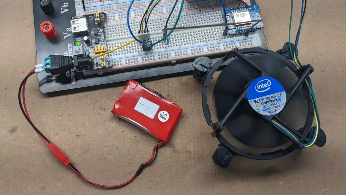
Step 1: Gather the necessary tools and components: Before you begin, gather the following tools and components: the breadboard, the power supply unit, jumper wires, and any other components you intend to power in your circuit.
Step 2: Identify the positive and negative terminals: Locate the positive (+) and negative (-) terminals on your power supply unit. These will be marked on the PSU or outlined by color-coding. Typically, the positive terminal will be colored red, while the negative terminal will be colored black.
Step 3: Connect the power supply unit to the breadboard: Take a jumper wire and insert one end into the positive terminal of the PSU. Insert the other end into any hole along the positive power rail of the breadboard. Similarly, connect another jumper wire from the negative terminal of the PSU to any hole along the negative power rail of the breadboard. These connections will provide the power supply to the breadboard.
Step 4: Secure the connections: Ensure that the jumper wires are securely inserted into the terminal and breadboard. Loose connections can result in power interruptions or unreliable circuit behavior. Double-check that the wires are snugly positioned in the holes.
Step 5: Test the power supply unit: Before connecting any additional components, it’s essential to test the power supply unit. Use a multimeter to measure the voltage at various points on the breadboard to verify that the PSU is providing the desired voltage. Ensure that the voltage matches your circuit’s requirements.
Once you have successfully connected the power supply unit to the breadboard and verified its functionality, you can proceed to power your circuit by connecting the components to the appropriate rows and columns on the breadboard. Remember to follow the manufacturer’s guidelines and datasheets for any specific component wiring requirements.
By following these steps, you can establish a solid connection between the power supply unit and the breadboard, ensuring a stable and reliable power source for your circuits. Proper connections will help prevent any unexpected behavior and ensure successful prototyping and testing of your electronic projects.
Step 1: Gather the Necessary Tools and Components
Before you begin connecting the power supply unit (PSU) to the breadboard, it’s essential to gather all the necessary tools and components. Having everything prepared in advance will streamline the connection process and ensure a smooth workflow. Here’s a list of items you’ll need:
1. Breadboard: Select a breadboard that suits the size and complexity of your circuit. Breadboards come in various sizes, ranging from small mini breadboards to larger full-sized ones. Choose one that provides enough space for your components while allowing for easy connections.
2. Power Supply Unit (PSU): Ensure you have a suitable PSU that provides the required voltage and current for your circuit. Consider the specifications mentioned earlier, such as voltage range, current rating, and adjustable output, to select an appropriate PSU for your needs. Verify that the PSU has the necessary positive and negative terminals for connecting to the breadboard.
3. Jumper Wires: Jumper wires act as the conduits for transferring power from the PSU to the breadboard. These wires come in various lengths, colors, and types, such as male-to-male, male-to-female, and female-to-female. Select a set of jumper wires that are long enough to reach from the PSU to the breadboard comfortably.
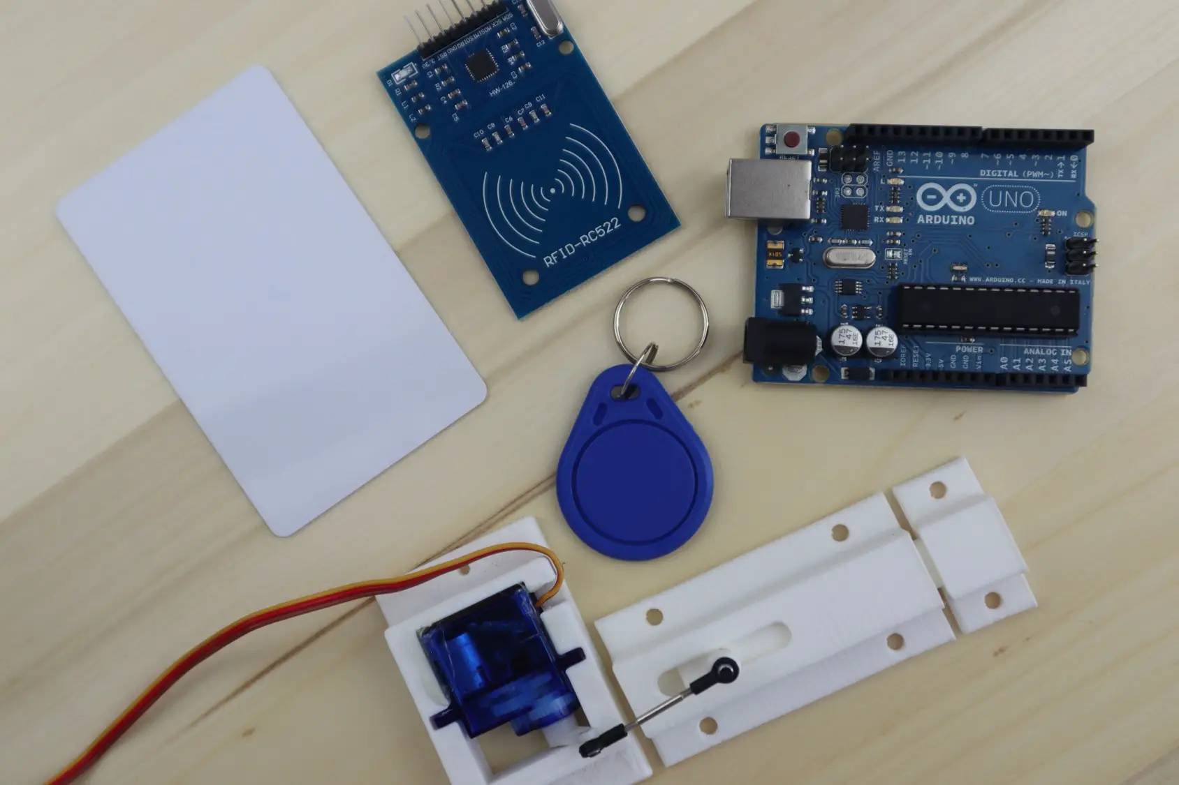
4. Components: Depending on your circuit design, gather all the components needed for your project. This may include resistors, capacitors, LEDs, ICs, and any other components required to complete your circuit. Ensure that you have the correct values and types of components as specified in your circuit diagram or project plan.
5. Toolkits: Keep a basic toolkit handy for trimming jumper wires, stripping insulation, and making other adjustments during the connection process. This toolkit may include wire cutters, wire strippers, needle-nose pliers, and a small screwdriver if needed.
By having all these tools and components ready, you can proceed with the connection process smoothly, minimizing interruptions and ensuring a more efficient workflow. Double-check that you have everything before moving on to the next steps.
Remember to work in a well-lit and organized workspace to make it easier to locate and handle your tools and components. Taking the time to gather the necessary items before starting will save you from unnecessary interruptions and allow you to focus on the task at hand – connecting the power supply unit to the breadboard.
Step 2: Identify the Positive and Negative Terminals
In the process of connecting a power supply unit (PSU) to a breadboard, it is crucial to identify the positive (+) and negative (-) terminals of the PSU. These terminals determine the direction of the electrical current flow and ensure the correct polarity for powering your circuit. Follow these steps to identify the positive and negative terminals:
1. Refer to the PSU documentation: Consult the product documentation or packaging that came with your PSU. Often, PSU manufacturers clearly label the positive and negative terminals, making it easy to identify them.
2. Color-coding: Many PSU models use color-coded terminals to indicate polarity. The positive terminal is commonly colored red, while the negative terminal is usually black. Look for any colored indicators, markings, or symbols on the PSU unit itself that denote polarity.
3. Check the connector: If you are using a detachable connector or cable to connect the PSU to the breadboard, examine the connector closely. Some connectors have built-in markings or indicators to denote positive and negative terminals.
4. Pay attention to the shape: In some cases, the positive and negative terminals of a PSU may have different shapes or sizes. For example, the positive terminal may be larger or have a different contour compared to the negative terminal. Examine the terminals closely to detect any physical differences.
It’s important to correctly identify the positive and negative terminals of the PSU to avoid damaging your circuit or components. An incorrect connection can result in reversed polarity, which can cause malfunction or even permanent damage to sensitive electronic components.
Once you have identified the positive and negative terminals of the PSU, take note of their positions for the next step of connecting the power supply unit to the breadboard. Ensuring the correct polarity will ensure that your circuit receives the appropriate power supply and operates correctly.
Remember, safety is paramount when working with electricity. Always double-check connections and follow the manufacturer’s guidelines for your specific PSU model to avoid any potential issues or hazards.
Step 3: Connect the Power Supply Unit to the Breadboard
With the positive and negative terminals of the power supply unit (PSU) identified, you are ready to connect it to the breadboard. This step is crucial as it establishes the power source for your circuits. Follow these instructions to connect the PSU to the breadboard:
1. Take a jumper wire: Grab a suitable jumper wire that will reach from the PSU to the breadboard comfortably. Ensure that the wire is long enough to span the distance without straining the connection.
2. Connect the positive terminal: Insert one end of the jumper wire into the positive (+) terminal of the PSU. Ensure that the connection is snug and secure. The positive terminal is commonly color-coded red or marked with a “+” symbol.
3. Connect the negative terminal: Take the other end of the jumper wire and insert it into any hole along the negative (-) power rail of the breadboard. The negative terminal is typically color-coded black or marked with a “-” symbol.
4. Verify the connections: Double-check that the jumper wire is properly inserted into both the PSU and the breadboard. Ensure that there is a firm connection on both ends to prevent any power interruptions or loose connections.
By following these steps, you have successfully connected the power supply unit to the breadboard. The positive terminal of the PSU is now supplying power to the positive power rail of the breadboard, while the negative terminal is connected to the negative power rail.
It’s important to note that the power rails of the breadboard, also known as bus strips, run along the sides of the board. These rails provide a continuous power distribution system, allowing you to connect components easily and efficiently.
Properly connecting the PSU to the breadboard ensures a stable power source for your circuit. Make sure all connections are secure and double-check your circuit design or schematic to confirm that you have connected the correct terminals. This step sets the foundation for successfully powering and prototyping your electronic projects on the breadboard.
Step 4: Secure the Connections
After connecting the power supply unit (PSU) to the breadboard, it is essential to ensure that all the connections are secure. A loose or unreliable connection can lead to power interruptions or unstable circuit behavior. Follow these steps to secure the connections between the PSU and the breadboard:
1. Check the jumper wire connections: Examine both ends of the jumper wire that connects the PSU to the breadboard. Ensure that the wire is inserted firmly and fully into the terminals, both on the PSU and the breadboard. Wiggle the wire gently to ensure it is securely in place.
2. Verify the power rail connections: Confirm that the ends of the jumper wire are securely connected to the appropriate power rails on the breadboard. The positive wire should be connected to the positive power rail, and the negative wire to the negative power rail. Make sure there is a firm contact and no loose or wobbly connections.
3. Inspect for any bent pins or loose components: Thoroughly examine the breadboard to ensure that no pins or legs of components have become bent or dislodged during the connection process. Straighten any bent pins and verify that all components are securely inserted into the breadboard.
4. Use additional support if necessary: If you find that the jumper wire connections are not as secure as you would like, you can employ additional support. One method is to place adhesive tape or a small clamp on the jumper wire near the connection point. Be careful not to interfere with the other connections or accidentally short-circuit any components.
By taking these steps, you can ensure that the connections between the PSU and the breadboard are secure. A stable connection will prevent power loss, provide reliable power distribution, and maintain consistent functionality of your circuit.
Remember, a loose connection can easily become a source of frustration and potential problems in your circuits. Taking the time to verify and secure the connections will save you from unnecessary troubleshooting and ensure a smooth prototyping experience with your breadboard project.
Step 5: Test the Power Supply Unit
Once you have connected the power supply unit (PSU) to the breadboard and secured the connections, it is crucial to test the PSU before proceeding with your circuit. Testing the power supply ensures that it is providing the correct voltage and functioning properly. Follow these steps to test the power supply unit:
1. Prepare the multimeter: Set your multimeter to the appropriate voltage measurement setting that matches your circuit’s power requirements. For example, if your circuit requires a 5V power supply, set the multimeter to the DC voltage mode and select the 5V range.
2. Probe the power rail: Take the positive (+) probe of the multimeter and carefully touch it to any point along the positive power rail of the breadboard. Ensure that the probe makes good contact with the metal strip of the power rail.
3. Measure the voltage: With the positive probe in place, take the negative (-) probe of the multimeter and touch it to any point along the negative power rail of the breadboard. The multimeter should display the voltage reading provided by the PSU. Verify that the measured voltage matches the expected voltage for your circuit.
4. Check for stability: While keeping the multimeter probes in place, observe the voltage reading on the multimeter. Ensure that the voltage remains stable and does not fluctuate significantly. Stability in voltage is crucial for the proper functioning of your circuit components.
5. Repeat the measurement: If necessary, repeat the measurement at different points along the power rail to ensure consistent voltage levels. This helps identify any potential issues with the power supply distribution across the breadboard.
By testing the power supply unit at the breadboard, you can verify that it is providing a stable and accurate voltage to power your circuit. This step is essential for ensuring the correct operation of your electronic components and preventing any potential damage.
If the measured voltage differs significantly from the expected voltage or if the voltage is unstable, double-check all the connections and retest. If the issue persists, consider trying a different power supply unit or consulting a knowledgeable individual or an electronics expert for assistance.
Testing the power supply unit helps alleviate potential problems related to power before proceeding with connecting and powering your circuit components. By ensuring a stable power supply, you can move forward with confidence in building and testing your circuit on the breadboard.
Conclusion
In this tutorial, we have explored the process of connecting a power supply unit (PSU) to a breadboard. By following the step-by-step instructions, you can establish a reliable and stable power source for your breadboard circuits. Let’s recap the key points covered in this tutorial:
– We began by understanding why using a power supply unit is advantageous, including its stability, voltage control, higher current capacity, cost-effectiveness, and eco-friendliness.
– We then discussed the overview of a breadboard, highlighting its power rails and the interconnected rows and columns that provide a convenient platform for building circuits without soldering.
– The important considerations for choosing a power supply unit were outlined, including voltage requirements, current rating, adjustable output, noise and ripple, short circuit and overload protection, reliability, and budget.
– The step-by-step process for connecting the power supply unit to the breadboard was explained, covering gathering the necessary tools and components, identifying the positive and negative terminals, making the connections, securing them, and testing the power supply.
Ensuring a proper connection between the power supply unit and the breadboard is essential for a successful electronics project. It provides a stable power source, allowing you to focus on prototyping and testing your circuits without interruptions caused by unreliable power.
Remember to work in a well-organized and safe environment, following the manufacturer’s instructions for both the power supply unit and the breadboard. Always double-check the connections and test the power supply to verify that it meets the voltage requirements.
By mastering the process of connecting a power supply unit to a breadboard, you have gained a fundamental skill in electronics prototyping. Harness the stability and reliability of the power supply unit to power your creative ideas and bring your electronic projects to life.