Introduction
Welcome to the world of DIY computer customization! If you’re looking to enhance the cooling capabilities of your PC case, controlling the speed of your fans can be a game-changer. In this guide, we will walk you through the process of building a circuit to control a 4-pin PC case fan.
Why would you want to control the speed of your case fan? Well, it can help optimize the airflow inside your PC, keeping your components cool and extending their lifespan. By adjusting the fan speed, you can also reduce noise levels, creating a quieter computing environment.
Now, you might be wondering, “What exactly is a 4-pin PC case fan?” A 4-pin fan is a type of cooling fan that uses a 4-pin connector for power and control. These fans have a unique feature called pulse-width modulation (PWM), which allows for precise control of fan speed. By modifying the duty cycle of the PWM signal, you can adjust the fan speed accordingly.
In this tutorial, we will provide a step-by-step guide on how to build the circuit to control a 4-pin PC case fan. You don’t need to be an electronics expert or have extensive programming knowledge. All you need is some basic tools and components, along with a willingness to dive into the world of DIY PC modifications.
Before we dive in, let’s take a quick look at what you will need for this project.
What You Will Need
Before you start building the circuit to control your 4-pin PC case fan, make sure you have the following materials and tools:
- A 4-pin PC case fan: Ensure that the fan you choose has a 4-pin connector and supports PWM (pulse-width modulation) control. This type of fan will give you the ability to adjust the fan speed.
- Jumper wires: These wires will be used to connect various components of the circuit. Make sure you have a set of male-to-male jumper wires.
- An Arduino board: We will be using an Arduino board as the microcontroller to control the fan speed. Any Arduino board, such as the Arduino Uno or Arduino Nano, will work for this project.
- An Arduino USB cable: This cable is necessary to connect the Arduino board to your computer.
- A breadboard: A breadboard will act as a platform to prototype and test the circuit before assembling it permanently.
- A potentiometer: The potentiometer will serve as the control mechanism to adjust the fan speed. Make sure you choose a potentiometer with a suitable resistance range for your needs.
- Some resistors: You will need a couple of resistors to protect the Arduino pins from excessive current.
- Female-to-male jumper wires: These wires will be used to connect the circuit components to the Arduino board.
- A soldering iron and solder: Although not mandatory, having a soldering iron and solder can help create secure and reliable connections between components.
- A PC case with fan mounting options: Finally, make sure you have a PC case with available fan mounting locations. You will need a place to install the controlled fan once the circuit is complete.
Once you have gathered all these materials, you will be ready to proceed with building the circuit.
Understanding the Components
Before we start building the circuit to control a 4-pin PC case fan, let’s take a moment to understand the key components involved:
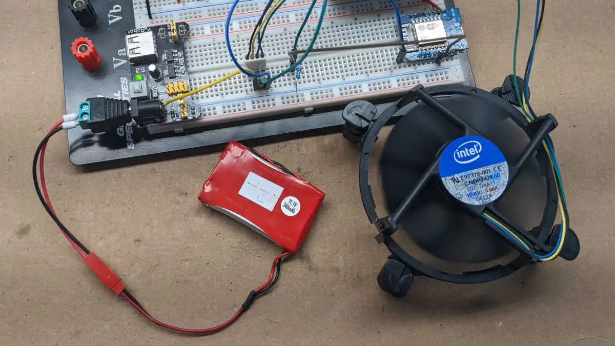
1. 4-Pin PC Case Fan: The PC case fan is the primary component that we will be controlling. It is specifically designed for cooling computer components and has four pins for power, ground, tachometer feedback, and PWM control. The PWM pin allows us to adjust the fan speed by changing the duty cycle of the control signal.
2. Arduino Board: We will be using an Arduino board as the microcontroller to control the fan speed. Arduino boards are popular among DIY enthusiasts due to their ease of use and versatility. They can be programmed using the Arduino IDE (Integrated Development Environment) and have a wide range of input and output capabilities that make them ideal for this project.
3. Breadboard: A breadboard is a platform used for prototyping circuits. It consists of a grid of holes that you can insert electrical components into and easily connect them using jumper wires. It allows you to test and modify your circuit before making any permanent connections.
4. Potentiometer: The potentiometer acts as a variable resistor that allows us to adjust the fan speed. It consists of a knob connected to a resistive track. By turning the knob, we can change the resistance and, therefore, the voltage or current in the circuit, ultimately controlling the fan speed.
5. Resistors: Resistors are passive electronic components that limit the flow of current in a circuit. In this project, we will use resistors to protect the Arduino pins from excessive current that could potentially damage them.
6. Jumper Wires: Jumper wires are essential for making connections between the various components in the circuit. They come in different colors and lengths and are used to transfer power, ground, and control signals between the Arduino board, the potentiometer, and the PC case fan.
With these components in mind, you are now equipped with the necessary knowledge to proceed with building the circuit and controlling the fan speed in your PC case. Let’s move on to the next section, where we will gather the materials required for this project.
Step 1: Gather the Materials
Before we dive into building the circuit to control your 4-pin PC case fan, let’s gather all the materials you will need:
- 4-pin PC case fan: Ensure that you have a 4-pin PC case fan that supports PWM (pulse-width modulation) control. This will allow you to adjust the fan speed as desired for optimal cooling.
- Arduino board: You will need an Arduino board to serve as the microcontroller for controlling the fan speed. Popular options include Arduino Uno, Arduino Nano, and Arduino Mega. Choose one that suits your preferences and availability.
- USB cable: Make sure you have a USB cable compatible with your Arduino board. This cable will be used to connect the Arduino board to your computer for programming and power.
- Breadboard: Get a breadboard to build and test the circuit before making any permanent connections. It will provide a convenient platform to prototype your circuit and ensure everything works correctly.
- Potentiometer: You will need a potentiometer, also known as a variable resistor, to control the fan speed. Choose a potentiometer with a suitable resistance range for your needs.
- Resistors: Select a couple of resistors to protect the Arduino pins from excessive current. The values will depend on the specifications of your fan and potentiometer.
- Jumper wires: Get a set of male-to-male and female-to-male jumper wires in various lengths. These wires will be used to connect the components together and make the necessary electrical connections.
- Soldering iron and solder: While not mandatory, having a soldering iron and solder can help create more secure and reliable connections between components. It may be useful for making permanent connections, especially if you plan to build the circuit onto a PCB (Printed Circuit Board).
- PC case with fan mounting options: Ensure that your PC case has available fan mounting locations. You will need a place to install the 4-pin PC case fan once the circuit is complete.
Once you have acquired all the necessary materials, you can proceed with the next steps. In the upcoming section, we will identify the pin configuration of the 4-pin PC case fan.
Step 2: Identify the Pin Configuration
Before we begin connecting the components, it’s crucial to identify the pin configuration of your 4-pin PC case fan. Understanding the pins and their functions will ensure that we make the correct connections later on.
Typically, a 4-pin PC case fan will have the following pins:
- Ground (GND): This is the ground pin that provides the reference voltage for the fan.
- Power (VCC): The power pin supplies the voltage for operating the fan motor. It is usually connected to a 5V pin on the Arduino board.
- Tachometer (TACH): The tachometer pin provides feedback about the fan speed to the Arduino board. This pin outputs a series of pulses per revolution of the fan motor.
- PWM Control (PWM): The PWM control pin allows us to adjust the fan speed by sending a PWM signal from the Arduino board. By varying the duty cycle of this signal, we can control the fan’s rotational speed.
It is essential to understand these pins because we will be connecting them to specific pins on the Arduino board in the next steps. If your fan has different pin configurations, consult the fan’s datasheet or manufacturer’s documentation to ensure you have the correct pin layout.
Take a close look at your 4-pin PC case fan and identify the pins marked with the ground, power, tachometer, and PWM control labels. Note their positions and make a mental or physical note of the pin assignments for future reference.
Now that we have identified the pin configuration of the 4-pin PC case fan, we are ready to move on to the next step: connecting the components.
Step 3: Connect the Components
With the pin configuration of your 4-pin PC case fan identified, it’s time to connect the components and build the circuit that will control the fan speed. Follow these steps to connect the various components:
- Connect the Arduino board: Plug your Arduino board into the breadboard, ensuring that it spans the center gap of the board. This will provide power and ground connections across the entire breadboard.
- Connect the potentiometer: Insert the potentiometer into the breadboard, making sure that it spans the gap across the center row. Connect one end of the potentiometer to the 5V pin on the Arduino, and the other end to the ground (GND) pin on the Arduino.
- Connect the resistors: Add the resistors to the breadboard. Connect one end of a resistor to the 5V pin on the Arduino board, and the other end to a free row on the breadboard. Repeat this for each resistor.
- Connect jumper wires: Take a male-to-male jumper wire and connect it from the potentiometer’s middle pin (wiper) to one end of a resistor. Connect another jumper wire from the same row of the resistor to the analog pin A0 on the Arduino board. These connections will allow the Arduino to read the voltage output of the potentiometer.
- Connect the PC case fan: Referencing the pin configuration from step 2, connect the ground (GND) pin of the PC case fan to a ground (GND) pin on the Arduino board. Connect the power (VCC) pin of the fan to the 5V pin on the Arduino. Connect the tachometer (TACH) pin to any digital input pin on the Arduino. Finally, connect the PWM control (PWM) pin of the fan to a digital PWM output pin on the Arduino (e.g., pin 9).
Once all the connections are made, double-check them to ensure they are correct and secure. Make any necessary adjustments or corrections before proceeding.
In the next step, we will assemble the circuit and start testing it to control the fan speed.
Step 4: Assemble the Circuit
Now that the components are connected, it’s time to assemble the circuit and prepare it for testing. Follow these steps to assemble the circuit:
- Secure the Arduino board: Make sure the Arduino board is firmly connected to the breadboard, spanning the center row where the power and ground connections are made. This will provide stability and ensure proper functionality.
- Position the potentiometer: Ensure that the potentiometer is positioned properly on the breadboard, allowing easy access to the knob for adjusting the fan speed.
- Attach the resistors: Make sure the resistors are firmly inserted into the breadboard and connected to the appropriate rows. Double-check that they are connected to the 5V pin on the Arduino and a free row on the breadboard.
- Mount the PC case fan: If your PC case has mounting spots for additional fans, secure the 4-pin PC case fan in a suitable location. Ensure that the fan is properly aligned and oriented to optimize airflow.
- Organize the jumper wires: Arrange the jumper wires, ensuring they are neatly connected between the components. This will help maintain a clean and organized circuit layout.
- Check the connections: Before proceeding to the next step, carefully inspect all the connections in the circuit. Ensure that there are no loose wires or incorrect connections that could cause issues later on.
Now that your circuit is properly assembled, it’s time to move on to the exciting part: testing the circuit and controlling the fan speed. In the next step, we will explore how to test the circuit and adjust the fan speed using the potentiometer.
Step 5: Test the Circuit
With the circuit assembled, it’s time to put it to the test and see if we can successfully control the fan speed. Follow these steps to test the circuit:
- Power up the Arduino: Connect the Arduino board to your computer using the USB cable. This will power up the Arduino and allow it to communicate with your computer.
- Upload the code: Open the Arduino IDE on your computer and write or copy the code for controlling the fan speed. Compile and upload the code to the Arduino board.
- Monitor the fan speed: Open the Serial Monitor in the Arduino IDE to monitor the fan speed. This will allow you to see the speed readings from the tachometer pin of the fan.
- Adjust the fan speed: Turn the knob on the potentiometer to adjust the fan speed. Notice how the speed changes in the Serial Monitor as you rotate the potentiometer.
- Observe the fan behavior: Keep an eye on the fan and listen to its sound. Notice how the speed changes affect the airflow and noise generated by the fan.
During the testing phase, make sure to observe any unusual behavior or unexpected results. If the fan speed does not respond or if there are any issues, double-check the connections and review the code for any errors.
Continue testing and adjusting the fan speed until you are satisfied with the results. Remember that the fan speed can be set to a specific value or varied continuously depending on your desired cooling and noise levels.
Once you have successfully tested the circuit and verified that you can control the fan speed, you are ready to move on to the final step: installing the fan in your PC case.
Step 6: Install the Fan in the PC Case
Now that you have tested and confirmed that the circuit is working correctly, it’s time to install the 4-pin PC case fan in your PC case. Follow these steps to install the fan:
- Choose the mounting location: Determine the ideal location within your PC case to install the fan. Look for an available mounting spot that will provide optimal airflow and cooling for your components.
- Prepare the mounting area: Ensure that the mounting area is clear of any debris or obstructions. Clean the area if necessary to promote good airflow and prevent any potential issues.
- Position the fan: Carefully align the screw holes on the fan with the corresponding holes in the mounting area. Ensure that the fan is positioned correctly for the most efficient airflow.
- Secure the fan: Using the appropriate screws or mounting brackets, secure the fan in place. Make sure the fan is tightly fastened to prevent any vibrations or movement during operation.
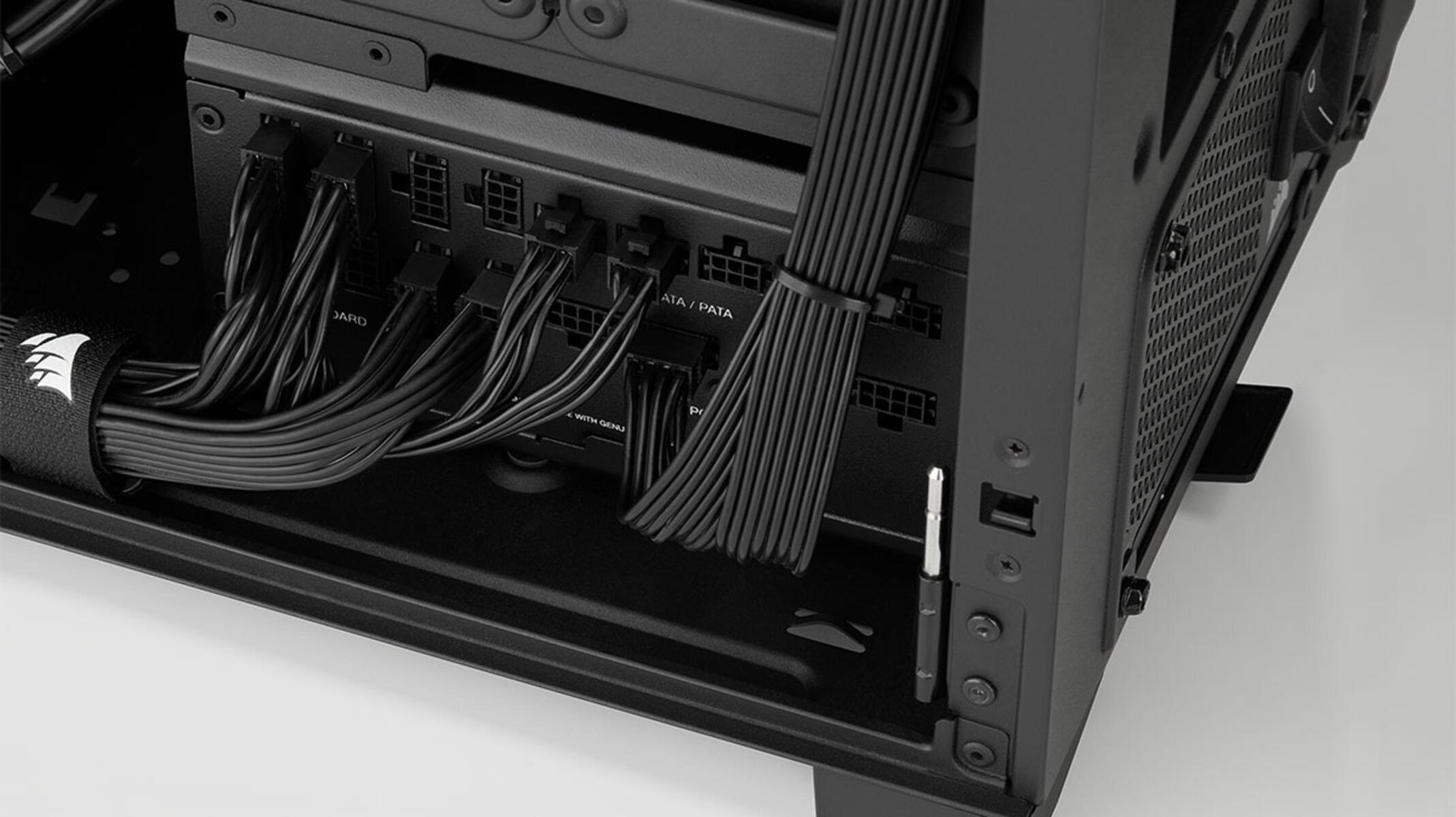
- Route the fan cable: Route the cable from the fan neatly to a suitable location within your case. This will ensure that the cable does not interfere with other components or obstruct airflow.
- Connect the fan cable: Plug the 4-pin connector from the fan into the corresponding header on the circuit, ensuring a secure and proper connection. This will allow the fan to receive power and control signals from the circuit.
- Double-check the connections: Before closing the PC case, verify that all the connections are secure and properly plugged in. Inspect the circuit and fan connections to ensure they are correctly connected.
Once you have completed the installation and confirmed that the fan is securely mounted inside the PC case, you’re ready to close the PC case and enjoy the benefits of controlling the fan speed.
Congratulations! You have successfully built a circuit to control a 4-pin PC case fan and installed it in your PC case. You now have the ability to fine-tune the fan speed for optimal cooling performance and reduced noise levels.
Remember to periodically monitor the fan performance and make any necessary adjustments based on your PC’s cooling requirements. Enjoy your improved cooling setup and the benefits it brings to your computer system!
Conclusion
Congratulations on successfully building a circuit to control a 4-pin PC case fan! With this circuit, you now have the ability to adjust the fan speed to optimize cooling performance and reduce noise levels in your PC case.
Throughout this guide, you have learned about the key components involved in controlling a 4-pin fan, including the fan itself, the Arduino board, and the potentiometer. By understanding the pin configuration and making the appropriate connections, you have built a functional circuit that allows you to control the fan speed.
Testing the circuit enabled you to observe how changing the fan speed affects the airflow and noise levels inside your PC case. This allows you to find the right balance between cooling performance and noise reduction, providing an optimized computing environment.
Once you were satisfied with the circuit’s performance, you successfully installed the 4-pin PC case fan in your PC case. By securing the fan in an ideal location and ensuring proper cable management, you have completed the project and can enjoy the benefits of a controlled fan speed.
Remember to periodically monitor the fan’s performance and make any necessary adjustments based on your PC’s cooling needs. Fine-tuning the fan speed will help maintain optimal temperatures and extend the lifespan of your computer components.
Keep in mind that this project is just one example of the many possibilities in the world of DIY computer customization. Exploring further and experimenting with different components and circuits can open up a world of opportunities for enhancing your PC’s performance and personalizing your setup.
We hope you found this guide informative and helpful. Enjoy your newly controlled PC case fan and the improved cooling capabilities it provides!