Introduction
Welcome to the world of PC case modding! If you’re an enthusiast looking to customize your PC case and enhance its cooling capabilities, building a circuit to control a 4 pin PC case fan is a great place to start. By having control over fan speed, you can optimize cooling performance while reducing noise levels, resulting in a more efficient and quiet system.
In this guide, we will walk you through the process of building a circuit to control a 4 pin PC case fan. Whether you’re a beginner or have some experience with electronics, this step-by-step tutorial will help you understand the basics and successfully complete the project. So, let’s dive in!
Before we get started, it’s important to have a basic understanding of how PC case fans work. These fans are typically designed with four pins, which include power, ground, and two control pins. The control pins allow you to adjust the fan speed using either voltage control or Pulse Width Modulation (PWM) control.
By harnessing the power of PWM control, you can achieve more precise and efficient fan speed regulation. PWM control adjusts the fan speed by rapidly switching the power on and off, effectively controlling the average voltage supplied to the fan. This method has become the preferred choice for controlling PC case fans due to its accuracy and versatility.
Now that you have a grasp on the fundamentals, let’s move on to the tools and materials you will need for this project.
Understanding the Basics
Before diving into the process of building a circuit to control a 4 pin PC case fan, let’s take a moment to understand the basic concepts involved.
As mentioned earlier, a 4 pin PC case fan consists of power, ground, and two control pins. The control pins allow you to adjust the fan speed using voltage control or PWM control. Voltage control works by varying the voltage supplied to the fan, while PWM control adjusts the average voltage supplied through rapid on and off cycles.
PWM control is the preferred method due to its advantages. By rapidly switching the power on and off, PWM control allows for more precise control over the fan speed and reduces power consumption. It also minimizes noise levels, making it an ideal choice for those seeking a quieter PC experience.
When using PWM control, it’s important to note that the fan itself needs to support this method. Most modern PC case fans come with PWM support, so you should have no trouble finding one. Make sure to check the fan’s specifications to ensure compatibility.
Furthermore, it’s worth understanding the concept of duty cycle when it comes to PWM control. Duty cycle refers to the percentage of time the power is switched on during a PWM cycle. For example, a duty cycle of 50% means the power is on for 50% of the time and off for the remaining 50%. By adjusting the duty cycle, you can effectively control the fan’s speed. A 100% duty cycle results in the fan running at full speed, while a lower duty cycle slows it down.
With a solid understanding of the basics, you’re ready to gather the necessary tools and materials to embark on your journey of building a circuit to control a 4 pin PC case fan. Let’s move on to the next section to explore what you’ll need.
Gather the Necessary Tools and Materials
Before you start building the circuit to control a 4 pin PC case fan, you’ll need to gather a few essential tools and materials. Here’s what you’ll need:
- Soldering Iron: A good quality soldering iron is necessary for soldering the components together.
- Soldering Wire: A spool of rosin-core soldering wire will be required for connecting the components.
- Wire Cutters: Wire cutters or snips will come in handy for trimming the excess wire.
- Wire Strippers: You’ll need wire strippers to remove the insulation from the ends of wires.
- Breadboard: A breadboard will serve as the platform for prototyping and testing the circuit.
- Jumper Wires: Assorted jumper wires are essential for making the necessary connections on the breadboard.
- Arduino or Microcontroller: You’ll need an Arduino or microcontroller with PWM capabilities to control the fan speed.
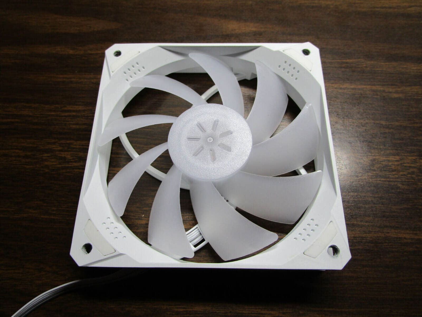
- 4 Pin PC Case Fan: Choose a 4 pin PC case fan that supports PWM control for optimal results.
- Resistors: Depending on the fan’s specifications, you may require resistors to adjust the voltage level.
- Prototyping Board (optional): If you prefer a more permanent solution, you can use a prototyping board for soldering the components.
Make sure to double-check the compatibility of the components and gather any additional tools or materials specific to your project. Once you have everything ready, you’re prepared to move on to the next section for the step-by-step instructions.
Step-by-Step Instructions
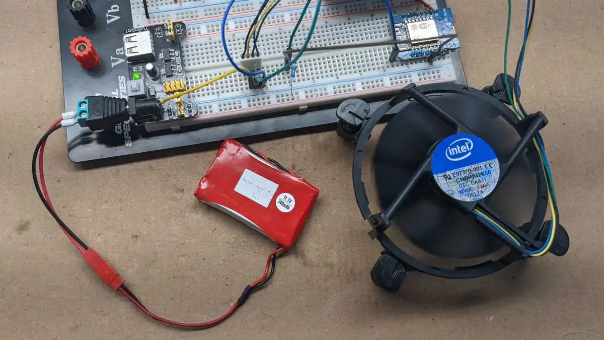
Now that you have all the necessary tools and materials, it’s time to start building the circuit to control a 4 pin PC case fan. Follow these step-by-step instructions:
- Start by preparing your breadboard. Connect the power and ground rails to the appropriate voltage sources.
- Next, place your Arduino or microcontroller on the breadboard. Ensure that it is securely connected to the power and ground rails.
- Locate the PWM pins on your Arduino or microcontroller. These pins will be used to control the fan speed.
- Connect one of the Arduino’s PWM pins to one of the fan’s control pins. Check your fan’s documentation for the specific pin to use.
- Connect the ground pin of the fan to the ground rail on the breadboard.
- If your fan requires voltage adjustment, calculate the resistor values needed to achieve the desired voltage level. Consult your fan’s specifications to determine the appropriate resistor values.
- Connect the resistor(s) between the power source and the other control pin of the fan. Ensure that the resistors are properly connected.
- Now it’s time to power up your circuit. Connect the power source to the appropriate rails on the breadboard. Make sure to double-check all connections for accuracy.
- Upload a PWM control sketch to your Arduino or microcontroller. This sketch will provide the necessary code to control the fan speed.
- Once the sketch is uploaded, you should be able to adjust the fan speed using the PWM control.
- Test the circuit and make any necessary adjustments to the resistor values for optimal performance.
Remember to follow safety precautions when working with electronics and soldering. Double-check all connections and ensure that everything is secure before powering on the circuit.
With the step-by-step instructions completed, you’re ready to move on to testing and troubleshooting the circuit.
Testing and Troubleshooting
After building the circuit to control a 4 pin PC case fan, it’s essential to test and troubleshoot to ensure everything is functioning correctly. Here are some steps to follow:
- Power on your circuit and observe the fan. It should start spinning at a default speed.
- Use the PWM control code on your Arduino or microcontroller to adjust the fan speed. Test different duty cycle values and observe the changes in fan speed accordingly.
- Confirm that the fan speed responds correctly to the PWM control, slowing down or speeding up as expected.
- Measure the voltage across the fan using a multimeter to ensure that the voltage adjustment, if applicable, is functioning correctly.
- Observe any unusual behavior, such as the fan not spinning, erratic speed changes, or strange noises. These could indicate a connection issue or a problem with the components.
- If you encounter issues, carefully check all the connections and make sure they are secure. Look for any loose wires or solder joints that may require fixing.
- If the fan is not spinning, double-check the wiring and ensure that the power and ground are connected correctly.
- If the fan’s speed is not changing with the PWM control, inspect the connections between the PWM pin and the fan’s control pin, ensuring they are properly connected.
- If the voltage adjustment is not working as intended, recheck the resistor values and connections.
- Make sure your Arduino or microcontroller is programmed correctly with the PWM control sketch.
- If troubleshooting steps do not resolve the issues, consult online resources or seek assistance from electronics forums to get further guidance.
Remember, patience is key when troubleshooting. Take your time to systematically identify and resolve any problems you encounter. With perseverance, you’ll be able to successfully debug your circuit and enjoy precise control of your PC case fan.
Once your circuit is tested, functioning properly, and you are satisfied with the fan speed control, it’s time to implement the circuit into your PC case. Securely mount the fan in your desired location, ensuring proper airflow for optimal cooling.
Congratulations! You have successfully built and tested a circuit to control a 4 pin PC case fan. Enjoy the benefits of customized fan speed control and a more efficient, quieter PC system.
Conclusion
Building a circuit to control a 4 pin PC case fan is an exciting DIY project that allows you to optimize cooling performance and reduce noise levels in your PC system. By understanding the basics, gathering the necessary tools and materials, following the step-by-step instructions, and conducting thorough testing and troubleshooting, you can successfully accomplish this project.
Through the use of PWM control, you can achieve more precise and efficient fan speed regulation, resulting in improved cooling performance and a quieter system. Additionally, voltage adjustment using resistors allows you to fine-tune the fan’s speed according to your specific needs.
During the process, it’s crucial to pay attention to safety precautions while working with electronics and soldering. Double-checking connections, ensuring secure wiring, and thoroughly testing the circuit are essential steps to ensure proper functionality.
With the completed circuit, you can enjoy the benefits of customizing your PC case fan’s speed control. Whether you prioritize silent operation for a noise-sensitive environment or require enhanced cooling in a high-performance system, having control over the fan’s speed offers flexibility and optimization.
As you gain confidence in your skills and understanding of electronics, you can expand your knowledge by exploring other PC case modding projects, such as LED lighting control or fan speed monitoring.
Remember, the journey of building circuits and modifying your PC case is a continuous learning experience. By utilizing the information and skills gained from this project, you can further enhance your PC customization abilities and create a personalized and efficient computer system.
So, get ready to unleash your creativity and embark on the journey of building and customizing circuits for your PC case fans. Start with this project, and soon you’ll be an expert in PC case modding!