Introduction
Welcome to the world of advanced security systems! In today’s digital age, traditional lock and key systems are being replaced by more innovative and sophisticated solutions. One such solution is the RFID sensor lock, which offers enhanced security and convenience. Whether you want to secure your home or office, an RFID sensor lock can provide an efficient and reliable access control mechanism.
An RFID sensor lock utilizes radio frequency identification (RFID) technology to grant or deny access to individuals. Unlike traditional locks that require physical keys, an RFID sensor lock uses RFID tags or cards to authenticate the user. When the valid RFID tag is placed near the sensor, the lock mechanism is activated, granting access to the authorized person.
RFID sensor locks offer several advantages over conventional lock and key systems. First and foremost, they eliminate the need for physical keys, reducing the risk of lost or stolen keys. Additionally, RFID sensor locks are more secure as they are difficult to tamper with compared to traditional locks. They also provide a smoother and faster entry process, eliminating the need for fumbling with keys.
If you are interested in harnessing the power of technology to enhance your home or office security, then building your own RFID sensor lock can be a fascinating and rewarding project. In this step-by-step guide, we will walk you through the process of making your own RFID sensor lock from scratch. You don’t need to be a tech expert to follow along, as the materials and instructions we provide are beginner-friendly.
So, without further ado, let’s dive into the world of RFID sensor locks and discover how to create one for your own security needs!
What is an RFID Sensor Lock?
An RFID sensor lock is a high-tech security device that uses radio frequency identification (RFID) technology to control access to a specific area or object. It functions by detecting and authenticating RFID tags or cards that are programmed for access. Unlike traditional lock and key systems, where physical keys are used, an RFID sensor lock provides a more advanced and convenient method of securing a space.
RFID technology has gained popularity in various industries due to its efficiency and ease of use. It utilizes electromagnetic fields to transmit data between an RFID reader and a tag. The reader emits a radio frequency signal, which activates the RFID tag in close proximity. The tag then transmits its unique identification information back to the reader, which verifies if the user has the necessary authorization to access the secured area.
The RFID sensor lock consists of two main components: an RFID reader module and an electronic lock mechanism. The RFID reader module is responsible for detecting and reading the data from the RFID tags. It communicates with the electronic lock, which controls the physical access to the secured area. When a valid RFID tag is presented to the reader, the lock mechanism is triggered, allowing entry to the authorized person.
One of the key advantages of an RFID sensor lock is the convenience it offers. With traditional locks, the user needs to carry and manage multiple keys, which can be cumbersome and increase the risk of losing them. However, with an RFID sensor lock, users can simply carry a lightweight RFID card or tag, eliminating the need for physical keys. This not only provides a hassle-free experience but also enhances security by reducing the chances of unauthorized key duplication.
RFID sensor locks are widely used in various applications, including residential homes, offices, hotels, and even vehicles. They offer a secure and efficient way to control access, ensuring that only authorized individuals can enter specific areas. Furthermore, RFID sensor locks can be integrated with other security systems, such as surveillance cameras and alarm systems, to create a comprehensive security solution.
Now that we have a basic understanding of what an RFID sensor lock is and the benefits it offers, let’s move on to the next section, where we will explore the components required to build one.
Components Required for an RFID Sensor Lock
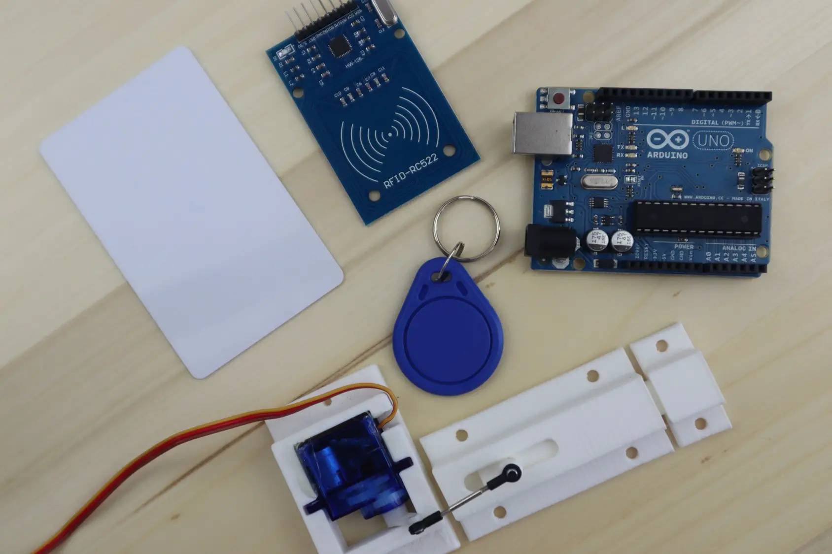
To build your own RFID sensor lock, you will need several key components. These components are readily available and can be easily obtained from electronics stores or online marketplaces. Here are the essential components required for creating an RFID sensor lock:
- RFID Reader Module: The RFID reader module is the heart of the system. It is responsible for detecting and reading the data from RFID tags. Look for an RFID reader module that supports the frequency and type of RFID tags you intend to use.
- RFID Tags or Cards: RFID tags or cards are the key to access the RFID sensor lock. These small devices contain unique identification information and are programmed to grant access. Ensure that the tags or cards you choose are compatible with your RFID reader module.
- Electronic Lock Mechanism: The electronic lock mechanism is what physically controls the access to the secured area. There are various types of electronic locks available, including solenoid locks, electromagnetic locks, or electronic strike locks. Choose a lock mechanism that suits your specific requirements.
- Arduino Board: An Arduino board acts as the brain of the RFID sensor lock system. It processes the signals from the RFID reader module and controls the electronic lock. Arduino Uno or Arduino Nano boards are commonly used for this purpose.
- Jumper Wires: Jumper wires are used to establish connections between the components. Make sure to have a variety of jumper wires with different lengths and male-to-male or male-to-female connectors.
- Power Supply: You will need a power supply to ensure the proper functioning of the RFID sensor lock system. This can be a USB power adapter or a battery pack, depending on your design preferences.
- Breadboard: A breadboard is a useful tool for prototyping and testing your circuit before finalizing the connections. It allows you to build and modify the circuit without soldering.
- Connecting Wires: Connecting wires are used to establish connections between the components on the breadboard or the Arduino board. They can be solid core or stranded wires, depending on your preference.
- Resistors and Capacitors: Depending on the specific requirements of your RFID reader module and electronic lock, you may need resistors and capacitors to regulate and stabilize the electrical signals in the circuit.
These are the main components you will need to build an RFID sensor lock. Additionally, you may require other basic tools such as a soldering iron, wire cutters, and a screwdriver for assembly and customization purposes. Before proceeding to the next section, ensure that you have gathered all the necessary components to avoid any interruptions during the construction process.
Step-by-Step Guide on How to Make an RFID Sensor Lock
Building your own RFID sensor lock may sound complex, but with the right guidance and materials, it can be an enjoyable and rewarding project. Follow these step-by-step instructions to create your own RFID sensor lock:
- Gathering the Materials: Collect all the components mentioned in the previous section, including the RFID reader module, RFID tags or cards, electronic lock mechanism, Arduino board, jumper wires, power supply, breadboard, connecting wires, resistors, and capacitors.
- Connecting the RFID Reader Module: Start by connecting the RFID reader module to the Arduino board. Refer to the datasheet or instructions provided with your particular RFID reader module for the specific wiring details. Use jumper wires to establish the necessary connections.
- Setting Up the Electronic Lock: Connect the electronic lock mechanism to the Arduino board. The wiring may vary depending on the type of lock mechanism you are using. However, typically you need to connect power, ground, and a control pin from the Arduino board to the lock mechanism.
- Adding the RFID Tags: Program your RFID tags or cards with unique identification information. Most RFID reader modules come with libraries and software that allow you to write and read data from the tags. Follow the instructions provided with your RFID reader module to program the tags and ensure they are compatible with the module.
- Testing and Troubleshooting: Once you have all the components connected, power up the system and test its functionality. Place an authorized RFID tag near the RFID reader module and check if the electronic lock mechanism unlocks. If everything works as expected, you can proceed to fine-tune the system and make any necessary adjustments. If any issues arise, double-check your connections and consult the datasheets or troubleshooting guides for your components.
Remember to refer to the documentation provided with your specific components for detailed instructions and wiring diagrams. Additionally, don’t hesitate to explore online tutorials and communities for additional guidance and support.
By following these step-by-step instructions, you will be able to create your own RFID sensor lock. Remember to take your time, be patient, and enjoy the process. Once completed, you will have a reliable and customized security solution that adds an extra layer of protection to your space.
Gathering the Materials
The first step in building an RFID sensor lock is to gather all the necessary materials. Having everything you need at the beginning will ensure a smooth and uninterrupted construction process. Here are the essential components you will need:
- RFID Reader Module: Choose an RFID reader module that is compatible with the type of RFID tags or cards you want to use. Look for modules that support the appropriate frequency and communication protocol.
- RFID Tags or Cards: Purchase RFID tags or cards that will work with your chosen RFID reader module. Ensure that the tags or cards are programmed correctly and have unique identification information.
- Electronic Lock Mechanism: Select the appropriate electronic lock mechanism for your RFID sensor lock. Consider factors such as the type of lock (solenoid, electromagnetic, or electronic strike), voltage requirements, and physical dimensions.
- Arduino Board: An Arduino board will serve as the brains of your RFID sensor lock system. Choose a compatible model, such as Arduino Uno or Arduino Nano, depending on your project requirements.
- Jumper Wires: Jumper wires are used to connect the components together. Have a variety of male-to-male and male-to-female jumper wires with different lengths to ensure flexibility and ease of connection.
- Power Supply: Determine the power supply you will need for your RFID sensor lock. It can be a USB power adapter or a battery pack, depending on your specific setup and portability requirements.
- Breadboard: A breadboard will provide a platform for prototyping and testing your circuit before finalizing the connections. Make sure to have a suitable-sized breadboard for your project.
- Connecting Wires: Prepare a set of connecting wires to establish the connections between components on the breadboard or Arduino board. Choose wire types (solid core or stranded) and gauges that are appropriate for your project.
- Resistors and Capacitors: Depending on your RFID reader module and lock mechanism, you may need resistors and capacitors to stabilize the electrical signals and ensure proper functionality.
It’s also important to have basic tools on hand, including a soldering iron, wire cutters, and a screwdriver, for any necessary assembly or customization. Properly organizing and arranging your materials before starting the construction process will save you time and prevent any unnecessary delays during assembly.
Once you have gathered all the materials, you are ready to move on to the next step: connecting the RFID reader module. With all the necessary components at your disposal, you can build your own RFID sensor lock and enhance the security of your space.
Connecting the RFID Reader Module
Now that you have gathered all the necessary materials, it’s time to connect the RFID reader module to your RFID sensor lock system. The RFID reader module is a crucial component that detects and reads the data from the RFID tags or cards. Follow these steps to establish the proper connections:
- Identify the Pins: Examine your RFID reader module and locate its pins. Typically, an RFID reader module will have pins for power, ground, and data. Refer to the documentation or datasheet provided with your specific module for the pin layout and functionality.
- Connect Power and Ground: Using jumper wires, make the necessary connections between the power and ground pins of the RFID reader module and the corresponding pins on the Arduino board. Ensure that you connect power (typically 5V) to power and ground to ground.
- Connect Data Pins: Determine the data pin(s) on your RFID reader module and connect it to an available digital pin on the Arduino board. Use a jumper wire to establish this connection. Take note of the specific pin you choose as you will need to refer to it in the programming phase.
- Verify Connections: Double-check all the connections to ensure they are secure and properly made. Make sure there are no loose wires or accidental short circuits that may cause issues later on.
- External Power: If your RFID reader module requires external power beyond what the Arduino board can provide, connect the appropriate power source (such as a separate power supply) to the module. This ensures that the module receives sufficient power to operate correctly.
It’s important to refer to the documentation or datasheet provided with your specific RFID reader module for any specific wiring considerations or configuration settings that may be necessary. Additionally, be mindful of polarities and voltage requirements to prevent any accidental damage to the components.
Once the RFID reader module is properly connected to the Arduino board, you have successfully completed the second step in building your RFID sensor lock. The next step involves setting up the electronic lock mechanism, bringing you closer to creating a fully functional and secure access control system.
Setting Up the Electronic Lock
With the RFID reader module connected, it’s time to set up the electronic lock mechanism for your RFID sensor lock. The electronic lock is responsible for physically controlling the access to the secured area. Follow these steps to configure and connect the lock mechanism:
- Choose the Right Lock Mechanism: Select the appropriate electronic lock mechanism based on your specific requirements. Consider factors such as the type of lock (solenoid, electromagnetic, or electronic strike), voltage compatibility, and physical dimensions. Ensure that the lock mechanism can be controlled electrically.
- Locate Control Pins: Identify the control pins on the electronic lock mechanism. These pins allow you to send signals to the lock to trigger its operation. Refer to the lock mechanism’s datasheet or documentation for the pin layout and functionality.
- Connect Power and Ground: Use jumper wires to establish connections between the power and ground pins of the electronic lock mechanism and the corresponding pins on the Arduino board. Ensure that you connect power (typically 12V or 24V) to power and ground to ground, adhering to the voltage requirements of the lock mechanism.
- Connections for Controlling the Lock: Depending on the lock mechanism, you may need to connect additional pins, such as a control pin or relay, to the Arduino board. This connection allows the Arduino to send the necessary signals to trigger the lock’s operation. Refer to the documentation or guidelines provided with your specific lock mechanism for the details of these connections.
- Verify Connections: Check all the connections to ensure they are secure and correctly made. Confirm that there are no loose wires or accidental short circuits.
- Powering the Lock: If the lock mechanism requires a separate power supply in addition to the Arduino board’s power, connect the appropriate power source to the lock mechanism. This ensures that the lock receives sufficient power to operate effectively.
As always, consult the datasheet or documentation provided with your chosen lock mechanism for any specific wiring considerations or configuration settings. Pay attention to polarities and voltage requirements to avoid any unintentional damage to the components.
Once you have completed the setup of the electronic lock mechanism, you have made significant progress in constructing your RFID sensor lock. The next step involves adding and programming the RFID tags or cards, bringing you closer to having a fully functional access control system in place.
Adding the RFID Tags
With the RFID reader module and electronic lock set up, the next step in building your RFID sensor lock is to add and program the RFID tags or cards. These tags will serve as the key to access the secured area. Follow these steps to add the RFID tags to your system:
- Prepare the RFID Tags: Ensure that the RFID tags or cards you have are compatible with your RFID reader module. Make sure they are properly programmed and have unique identification information. Many RFID reader modules come with accompanying software or libraries for programming the tags.
- Identify the RFID Tags: Assign each RFID tag a recognizable identifier or label. This will allow you to easily associate the tag with specific individuals or authorized access privileges.
- Add Tags to the System: Place each RFID tag near the RFID reader module, ensuring that it is within range for proper detection. Activate the RFID reader module and observe if it successfully reads the tag and displays the unique identification information.
- Program the RFID Tags: If necessary, follow the instructions provided with your RFID reader module to program the RFID tags with the appropriate access privileges. This typically involves using the accompanying software or library to write data to the tags.
- Test the RFID Tags: Once the tags have been programmed, test them by placing them near the RFID reader module and verifying that the reader can read the tags’ identification information. Ensure that the tags grant access to the electronic lock mechanism when authorized.
Remember to keep the RFID tags in a safe and secure place, as they are the access tokens for your RFID sensor lock. It’s also a good practice to have a record or log of the authorized tags, linking them to the corresponding individuals or access privileges.
Take the time to verify and test each RFID tag to ensure that they function correctly and provide the necessary access control. Troubleshoot any issues that arise, such as misreads or unauthorized access, before moving on to the final step.
Adding and programming the RFID tags brings your RFID sensor lock system closer to being fully operational. The last step involves testing and troubleshooting the entire system to ensure its smooth functionality and effectiveness.
Testing and Troubleshooting
Once you have completed the construction and setup of your RFID sensor lock, it’s crucial to thoroughly test the system and troubleshoot any potential issues. Follow these steps to ensure the smooth functionality of your RFID sensor lock:
- Functional Testing: Test the system by presenting an authorized RFID tag near the RFID reader module and observe if the electronic lock mechanism unlocks. Repeat the process with different authorized tags to verify consistent and reliable operation.
- Range and Sensitivity Testing: Assess the range and sensitivity of the RFID reader module by varying the distance between the tag and the module. Ensure that the module can detect and read the tag within the desired proximity.
- False Positive/Negative Testing: Conduct tests to evaluate potential false positives (unauthorized access granted) or false negatives (authorized access denied). Adjust the sensitivity and programming of the RFID reader module to minimize these occurrences.
- Troubleshooting: If any issues arise during testing, troubleshoot the system to identify and resolve the problem. Double-check the connections, confirm the programming of the RFID tags, and ensure that the power supply is adequate. Refer to the documentation or guidelines provided with your components for troubleshooting tips.
- Reprogramming and Reconfiguring: If necessary, reprogram or reconfigure the RFID reader module and tags to address any inconsistencies or errors in granting access to authorized individuals.
- Security Enhancements: Evaluate the overall security of your RFID sensor lock system. Consider implementing additional security measures, such as encryption of the RFID tag data or incorporating two-factor authentication for added security.
It’s essential to be patient and meticulous during the testing and troubleshooting phase. Thoroughly document any issues encountered and their corresponding solutions. This information will be valuable for future maintenance and upgrades.
Once you have resolved any issues and ensured the proper functionality of your RFID sensor lock, you can confidently deploy it to secure your designated area. Regularly monitor and maintain the system to ensure ongoing reliability and security.
By diligently testing and troubleshooting your RFID sensor lock system, you can optimize its performance and reliability, providing a robust and efficient access control solution for your intended application.
Conclusion
Congratulations on successfully building your own RFID sensor lock! You have learned how to assemble the necessary components, connect the RFID reader module, set up the electronic lock, add and program RFID tags, and thoroughly test and troubleshoot the system. By following these steps, you have created a customized access control solution that offers enhanced security and convenience.
An RFID sensor lock provides numerous benefits over traditional lock and key systems, including reduced risk of lost or stolen keys, increased security, and smoother access control processes. With the power of RFID technology, you can quickly and securely grant or deny access to authorized individuals.
Remember to document the functioning of your RFID sensor lock, making note of any modifications or enhancements you incorporated. This documentation will serve as a valuable resource for future reference and maintenance.
As you have now successfully built an RFID sensor lock, continue to explore and expand your knowledge of other security systems and technologies. Consider integrating your RFID sensor lock with other security measures, such as surveillance cameras or biometric scanners, to enhance the overall security of your space.
Building your own RFID sensor lock is not only a satisfying accomplishment but also a great way to gain hands-on experience in electronics and security systems. You can now enjoy the convenience and peace of mind that comes with having a personalized access control mechanism protecting your valuable assets.
Continue to refine and enhance your RFID sensor lock system as new technologies and advancements emerge. Stay updated with the latest developments in RFID technology to ensure the continued effectiveness and security of your access control solution.
With your RFID sensor lock in place, you have taken a proactive step towards safeguarding your space. Embrace the possibilities that technology offers and enjoy the increased security and convenience that your DIY RFID sensor lock brings!