Introduction
Are you tired of the conventional setup of your game controller? Do you wish to customize the functionality to better suit your gaming style? One common modification that gaming enthusiasts often seek is the rewiring of the potentiometer in the controller to switch the left and right functions. This alteration can significantly enhance the gaming experience, especially for those who prefer non-traditional configurations.
Rewiring the potentiometer in a game controller involves swapping the connections to the left and right analog sticks, effectively reversing their functions. This modification can be particularly beneficial for gamers who find the default layout uncomfortable or inefficient. By understanding the inner workings of potentiometers and following the step-by-step process of rewiring, you can tailor your controller to better accommodate your gaming preferences.
In this guide, we will delve into the intricacies of potentiometers in game controllers, the tools and materials needed for this modification, the disassembly and identification of potentiometer connections, the rewiring process, testing the modified controller, and finally, reassembling the controller. By the end of this tutorial, you will have the knowledge and skills to rewire the potentiometer in your game controller, allowing you to switch the left and right functions to your liking. Let's embark on this journey to customize and elevate your gaming experience!
Understanding Potentiometers in Game Controllers
Before delving into the process of rewiring a game controller’s potentiometer, it’s essential to grasp the fundamental role of potentiometers in the device’s functionality. A potentiometer, often referred to as a “pot,” is a variable resistor that regulates the flow of electric current. In the context of game controllers, potentiometers are crucial components responsible for translating the physical movement of analog sticks into digital signals that the gaming console can interpret.
Game controllers typically feature two potentiometers, one for each analog stick. These potentiometers are designed to measure the position of the analog stick along its axis, generating corresponding voltage outputs. When the analog stick is moved, the wiper of the potentiometer adjusts the resistance, resulting in a change in voltage. This voltage alteration is then converted into digital signals, allowing the console to interpret the direction and magnitude of the stick’s movement.
Understanding the inner workings of potentiometers is paramount when considering a modification such as rewiring for left and right switching. By comprehending how potentiometers function and how their connections dictate the controller’s behavior, you can effectively reconfigure the wiring to achieve the desired outcome. This insight empowers gamers to tailor their controllers to suit their individual preferences, ultimately enhancing their gaming experience.
As we proceed with this guide, we will explore the intricate details of potentiometers, providing you with a comprehensive understanding of their role in game controllers. Armed with this knowledge, you will be well-equipped to embark on the process of rewiring the potentiometer in your game controller, paving the way for a customized and optimized gaming setup tailored to your unique style and preferences.
Tools and Materials Needed
Before embarking on the rewiring process, it’s crucial to gather the necessary tools and materials to ensure a smooth and successful modification of the game controller’s potentiometer. Here’s a comprehensive list of the items you will need:
- Screwdriver set: To facilitate the disassembly of the controller, you will require a set of precision screwdrivers suitable for the specific screws used in the controller’s construction.
- Soldering iron and solder: Since the rewiring process involves altering the connections within the controller, a soldering iron and high-quality solder are essential for securely joining and insulating the wires.
- Desoldering pump or wick: In the event of any mistakes or the need to remove existing solder connections, a desoldering pump or wick will be indispensable for effectively removing excess solder.
- Wire cutters and strippers: These tools are necessary for cutting and stripping the wires, ensuring precise and clean connections during the rewiring process.
- Electrical tape or heat shrink tubing: To insulate the newly connected wires and prevent short circuits, electrical tape or heat shrink tubing is essential for securing the connections and ensuring electrical safety.
- Multimeter: A multimeter will be invaluable for testing and verifying the continuity and resistance of the connections, ensuring the accuracy of the rewiring process.
- Replacement potentiometer (optional): Depending on the specific modification and the condition of the existing potentiometer, you may opt to use a replacement potentiometer to achieve the desired functionality.
By assembling these tools and materials, you will be well-prepared to undertake the rewiring process with confidence and precision. It’s essential to prioritize safety and accuracy throughout the modification, and having the right equipment at your disposal will contribute to a successful and satisfying outcome.
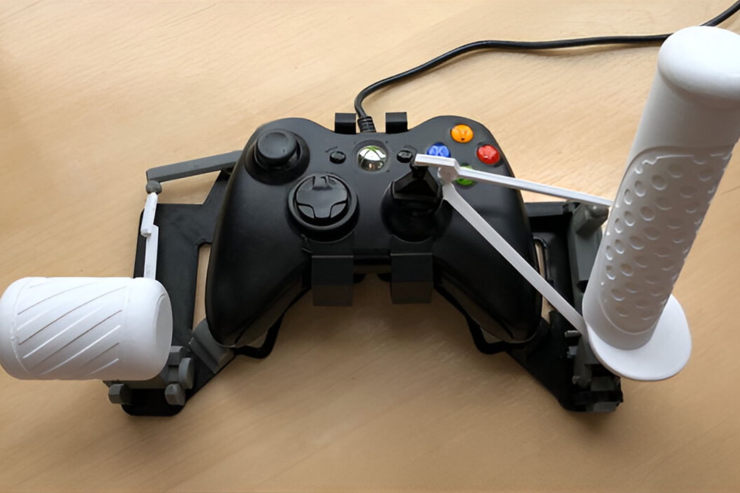
Disassembling the Controller
Before you can access the potentiometer and begin the rewiring process, you will need to disassemble the game controller carefully. This step is crucial to gain access to the internal components, including the potentiometers, and it requires precision and attention to detail. Here’s a step-by-step guide to disassembling the controller:
- Prepare a Clean Workspace: Find a well-lit, spacious area to work in, ensuring that you have ample room to lay out the controller components as you disassemble them.
- Remove the Battery: If your controller is battery-powered, remove the battery to prevent any electrical mishaps during the disassembly process.
- Identify and Remove Screws: Using the appropriate screwdriver from your set, carefully locate and remove the screws securing the controller’s casing. Keep the screws organized to facilitate reassembly later.
- Separate the Casing: Gently pry apart the controller’s casing, taking care not to damage any internal components or cables. Pay attention to any hidden latches or clips that may be securing the casing.
- Document the Disassembly: As you proceed, consider taking photos or making notes to document the disassembly process. This documentation can be invaluable when reassembling the controller later.
- Access the Internal Components: Once the casing is removed, you will have access to the internal circuitry and components, including the potentiometers that you will be working with.
It’s essential to approach the disassembly process with patience and caution, as rushing or applying excessive force can lead to damage or misalignment of the controller’s components. By meticulously following these steps and handling the controller with care, you will successfully prepare the device for the subsequent identification and rewiring of the potentiometer connections.
Identifying the Potentiometer Connections
Once the controller is disassembled, the next crucial step in rewiring the potentiometer involves identifying the specific connections that correspond to the left and right analog sticks. This process requires careful observation and, in some cases, the use of a multimeter to verify the connections. Here’s a detailed guide to identifying the potentiometer connections:
- Locate the Potentiometers: Within the controller, identify the potentiometers associated with the left and right analog sticks. These components are typically positioned near the base of the analog sticks and are connected to the controller’s circuit board.
- Understand the Wiring: Examine the existing wiring and connections leading from the potentiometers to the circuit board. Take note of the color-coding or labeling of the wires, as this information will be instrumental in identifying the connections for each analog stick.
- Use a Multimeter (Optional): If the wiring is not clearly labeled or color-coded, a multimeter can be employed to test the continuity and resistance of the connections. By probing the wires and observing the multimeter readings, you can ascertain which connections correspond to the left and right potentiometers.
- Document the Connections: As you identify the connections, consider documenting them using a diagram or labeled reference points. This documentation will serve as a valuable reference during the rewiring process, ensuring that the correct connections are modified.
- Verify the Functionality: Before proceeding with the rewiring, it’s advisable to verify the functionality of the potentiometers and their connections by testing the analog sticks’ movements. This step can help confirm the accuracy of the identified connections.
By meticulously identifying the potentiometer connections for the left and right analog sticks, you will lay the groundwork for the subsequent rewiring process. This phase requires attention to detail and a methodical approach to ensure that the modifications are accurately implemented, ultimately leading to the desired reversal of the left and right functions in the game controller.
Rewiring the Potentiometer for Left and Right Switching
With the potentiometer connections identified, the rewiring process can commence. This pivotal step involves carefully modifying the wiring to switch the functions of the left and right analog sticks, ultimately customizing the controller to better suit your preferences. Here’s a comprehensive guide to rewiring the potentiometer:
- Prepare the Wiring: Begin by carefully cutting and stripping the wires leading from the potentiometers to the circuit board. Exercise precision to ensure that the exposed wire ends are clean and free from any damage.
- Swap the Connections: Based on the documentation and identification of the potentiometer connections, proceed to swap the wiring for the left and right analog sticks. This entails connecting the wires originally associated with the left potentiometer to the terminals designated for the right potentiometer, and vice versa.
- Soldering the Connections: Using a soldering iron and high-quality solder, securely join the swapped wires to their respective terminals on the potentiometers and the circuit board. Ensure that the connections are robust and free from any short circuits or loose solder joints.
- Insulate the Connections: Once the rewiring is complete, insulate the newly connected wires using electrical tape or heat shrink tubing. This insulation is vital for preventing any electrical interference or short circuits within the controller.
- Verify the Connections: After completing the rewiring, use a multimeter to verify the continuity and resistance of the modified connections. This step is crucial for confirming the accuracy and integrity of the rewiring process.
By meticulously following these steps, you can effectively rewire the potentiometer to achieve the desired left and right switching in the game controller. It’s essential to approach the rewiring process with patience and precision, ensuring that the connections are accurately modified and securely insulated to guarantee the functionality and safety of the controller.
Testing the Rewired Controller
After completing the rewiring process, it’s crucial to thoroughly test the modified game controller to ensure that the left and right functions have been successfully switched. This testing phase allows you to verify the functionality of the analog sticks and confirm that the rewiring has achieved the desired outcome. Here’s a detailed guide to testing the rewired controller:
- Power Up the Controller: Reassemble the controller and power it up to initiate the testing phase. Ensure that all components are securely reassembled to avoid any interference with the testing process.
- Test the Analog Sticks: Use a compatible gaming console or software that allows you to test the input from the analog sticks. Move the analog sticks in various directions to observe their responsiveness and ascertain whether the left and right functions have been effectively switched.
- Verify the Inverted Functions: Pay close attention to the behavior of the analog sticks, particularly noting any inversion of the left and right functions. For example, moving the left analog stick to the right should result in the corresponding movement typically associated with the right analog stick.
- Assess Sensitivity and Accuracy: Evaluate the sensitivity and accuracy of the rewired analog sticks, ensuring that their responsiveness and precision align with your gaming preferences. Make any necessary adjustments if the sensitivity or calibration requires fine-tuning.
- Test in Gameplay: For a comprehensive assessment, test the rewired controller in actual gameplay scenarios across various games and genres. This real-world testing allows you to gauge the practical impact of the rewiring on your gaming experience.
By rigorously testing the rewired controller, you can confidently confirm the success of the modification and its alignment with your gaming preferences. This phase provides an opportunity to make any final adjustments and ensures that the customized controller delivers the intended left and right switching functionality, ultimately enhancing your gaming experience.
Reassembling the Controller
Once the rewiring and testing phases are successfully completed, the final step involves reassembling the game controller to restore it to its original form while incorporating the customized modifications. Reassembly is a critical phase that demands attention to detail and precision to ensure the controller’s functionality and structural integrity are maintained. Here’s a comprehensive guide to reassembling the controller:
- Organize the Components: Lay out the disassembled components in an organized manner, ensuring that all screws, cables, and internal parts are easily accessible for reassembly.
- Position the Casing: Begin by carefully aligning the controller’s casing, ensuring that any internal components, such as circuit boards and button mechanisms, are properly positioned within the casing.
- Secure the Casing: Gradually fasten the screws to secure the controller’s casing, taking care not to overtighten or cross-thread the screws. Follow the reverse order of the disassembly process to ensure all components are securely fastened.
- Reinstall the Battery (if applicable): If the controller is battery-powered, reinsert the battery and ensure it is properly seated and secured within the device.
- Test the Buttons and Functions: Before finalizing the reassembly, perform a brief functionality test to verify that all buttons, triggers, and other controls are responsive and function as expected.
- Verify the Analog Stick Functions: Specifically focus on testing the rewired analog sticks to confirm that the left and right switching functions operate seamlessly and align with your gaming preferences.
By methodically reassembling the controller and conducting comprehensive functionality tests, you can ensure that the customized modifications, including the rewiring of the potentiometer for left and right switching, integrate seamlessly into the controller’s structure. This meticulous approach guarantees that the controller not only reflects your personalized gaming preferences but also maintains its original functionality and reliability.
Conclusion
Embarking on the journey to rewire the potentiometer in a game controller for left and right switching is a rewarding endeavor that empowers gamers to tailor their gaming experience to their unique preferences. By understanding the fundamental role of potentiometers, meticulously disassembling the controller, identifying the potentiometer connections, and executing the rewiring process with precision, enthusiasts can customize their controllers to better suit their gaming style.
The process of rewiring the potentiometer requires careful attention to detail, patience, and a methodical approach to ensure the accuracy and integrity of the modifications. From preparing the necessary tools and materials to meticulously reassembling the controller, each phase contributes to the successful customization of the gaming device.
Through rigorous testing and real-world gameplay scenarios, gamers can confidently verify the effectiveness of the rewiring, ensuring that the left and right switching functions align with their gaming preferences. This hands-on approach allows for adjustments and fine-tuning to achieve the desired sensitivity and responsiveness in the rewired analog sticks.
Ultimately, the ability to rewire the potentiometer in a game controller for left and right switching provides a platform for gamers to elevate their gaming experience, fostering a sense of ownership and personalization. This customization empowers individuals to optimize their controllers to align with their gaming preferences, ultimately enhancing their immersion and enjoyment during gameplay.
As you embark on the process of rewiring the potentiometer in your game controller, remember that patience, precision, and attention to detail are key to achieving a successful outcome. By embracing the customization journey, you can transform your gaming experience and unlock new levels of comfort and control in your gameplay.