




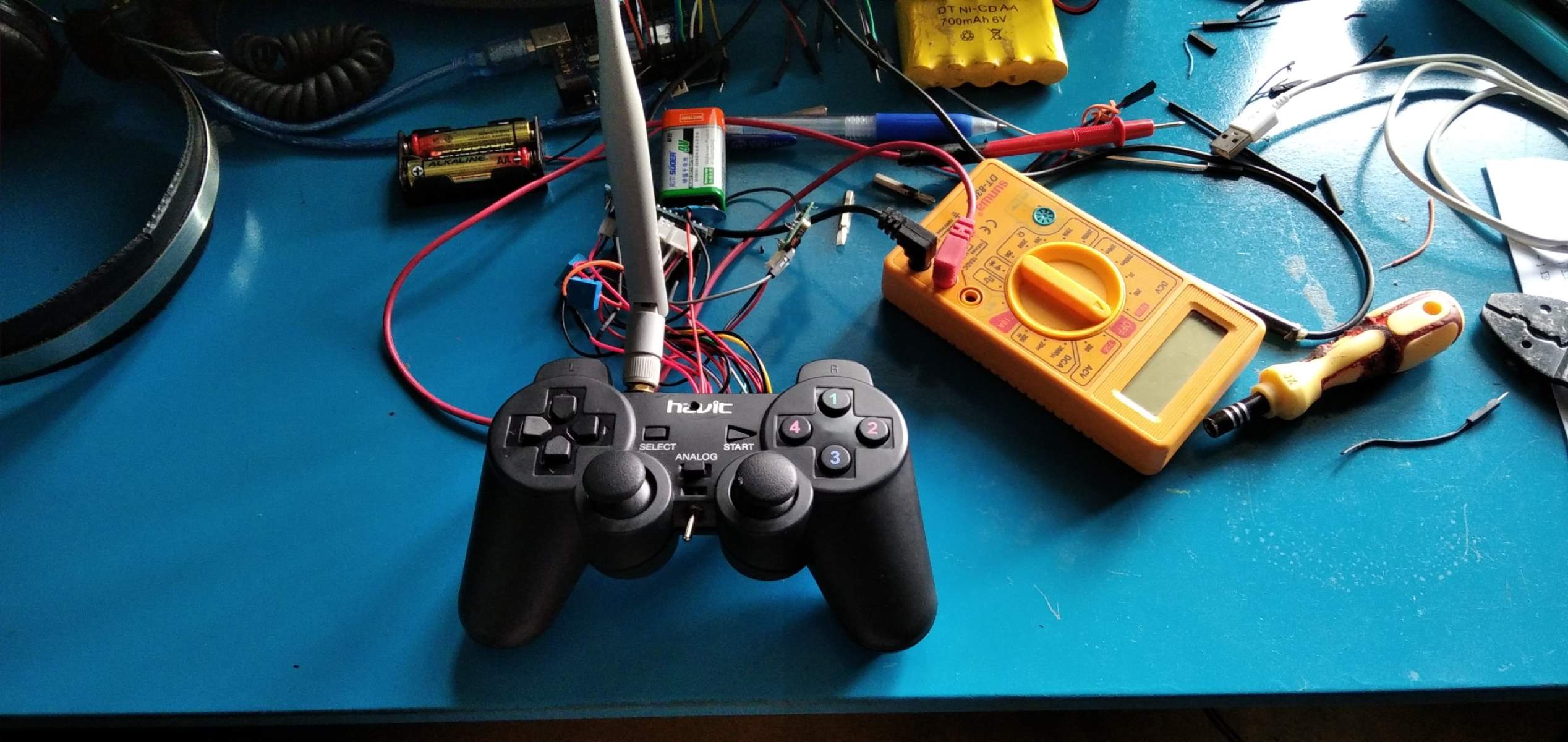
Can you make an Arduino uno game controller?
Yes, you can make an Arduino uno game controller, but the path depends entirely on which version of the Uno you own. The standard Arduino Uno R3 uses a separate ATmega16U2 chip purely for USB-to-serial communication, so it cannot act as a gamepad out of the box, you must flash new firmware onto that chip. The newer Arduino Uno R4 Minima and R4 WiFi, however, have built-in native USB HID support, meaning they can emulate a game controller directly from the Arduino IDE without any firmware hacking. If you have a clone with a CH340 USB chip, stop here: those boards cannot be converted to HID at all, so you’ll need a genuine Uno or an R4.
Materials needed for your DIY controller
Before you start, gather the components that turn a bare Uno into a functional gamepad. You’ll need an Arduino Uno (R3 or R4), a USB cable for programming and power, push buttons for action inputs, a joystick module for directional control, and potentiometers for analog axes like throttle or steering. A breadboard and jumper wires let you prototype the circuit without soldering, while resistors are essential for button debouncing to prevent false triggers. If you want a permanent build, add an enclosure or casing, plus a soldering iron and solder to secure connections. A computer running the Arduino IDE completes the setup, you’ll use it to write, upload, and test your code.
Flashing HID firmware on an Arduino Uno R3
If you’re using an Uno R3, the critical step is reprogramming the ATmega16U2 chip that handles USB communication. This chip normally translates serial data, but with custom firmware it can present the board as a USB gamepad. The process requires a DFU (Device Firmware Update) utility, `dfu-programmer` works on Linux and macOS, while Atmel’s Flip is the Windows option, plus a HID firmware `.hex` file designed for the Uno. To begin, put the ATmega16U2 into DFU mode by shorting specific pins on the board; on most Unos, this means bridging the two pins near the USB connector labeled “DFU” or using a jumper wire between the RESET and GND pins while plugging in the USB cable. Once in DFU mode, your computer will detect the chip as a generic USB device, and you can run the flashing command to overwrite the serial firmware with the HID version. After flashing, unplug the board, remove the jumper, and reconnect it, the Uno will now enumerate as a game controller instead of a serial port. Be aware that this permanently changes the board’s USB behavior, so you’ll need to repeat the DFU process if you ever want to restore serial communication for normal sketches.
Wiring the physical controller components
With the firmware ready, it’s time to connect your physical inputs to the Arduino’s pins. Plan your layout on the breadboard first, keeping button placement ergonomic and joystick positioning comfortable for your hand. Use jumper wires to link each component to the correct pin, and always double-check connections before powering the board. The table below shows a standard pin mapping that works with the code in the next section.
| Component | Arduino Pin |
|---|---|
| Button 1 | Digital 2 |
| Button 2 | Digital 3 |
| Button 3 | Digital 4 |
| Button 4 | Digital 5 |
| Joystick X-axis | Analog A0 |
| Joystick Y-axis | Analog A1 |
| Potentiometer 1 | Analog A2 |
| Potentiometer 2 | Analog A3 |
For each button, connect one leg to the digital pin and the other leg to GND through a 10kΩ resistor (pull-down configuration). The joystick module typically has five pins: VCC to 5V, GND to GND, and the X and Y outputs to the analog pins listed. Potentiometers use all three legs, outer pins to 5V and GND, the wiper to the analog input. Once everything is wired, test each input by reading the values in the serial monitor before moving to the code.
Writing the game controller code
Now you’ll write the sketch that turns raw electrical signals into gamepad actions. The code below uses the Arduino Joystick library, which handles HID communication for both R3 (after firmware flash) and R4 (native). Copy this into the Arduino IDE, select your board and port, and upload.
#include <Joystick.h>
Joystick_ Joystick(JOYSTICK_DEFAULT_REPORT_ID, JOYSTICK_TYPE_GAMEPAD,
4, 0, // 4 buttons, no hat switch
true, true, true, true, // X, Y, Z, and rotate axes
false, false, false, false, false, false);
const int buttonPins[] = {2, 3, 4, 5};
const int numButtons = 4;
const int joyXPin = A0;
const int joyYPin = A1;
const int pot1Pin = A2;
const int pot2Pin = A3;
int buttonStates[numButtons];
void setup() {
for (int i = 0; i < numButtons; i++) {
pinMode(buttonPins[i], INPUT_PULLUP);
buttonStates[i] = HIGH;
}
Joystick.begin();
}
void loop() {
// Read buttons with debouncing
for (int i = 0; i < numButtons; i++) {
int currentState = digitalRead(buttonPins[i]);
if (currentState != buttonStates[i]) {
delay(5); // debounce delay
currentState = digitalRead(buttonPins[i]);
if (currentState != buttonStates[i]) {
buttonStates[i] = currentState;
Joystick.setButton(i, currentState == LOW);
}
}
}
// Map analog inputs to joystick range (-127 to 127)
int joyX = map(analogRead(joyXPin), 0, 1023, -127, 127);
int joyY = map(analogRead(joyYPin), 0, 1023, -127, 127);
int pot1 = map(analogRead(pot1Pin), 0, 1023, -127, 127);
int pot2 = map(analogRead(pot2Pin), 0, 1023, -127, 127);
Joystick.setXAxis(joyX);
Joystick.setYAxis(joyY);
Joystick.setZAxis(pot1);
Joystick.setRotate(pot2);
delay(10);
}
This code initializes the joystick as a gamepad with four buttons and four analog axes. For an R4 board, this same code works without any firmware changes because the native HID support is built into the microcontroller. If you’re using an R3, the firmware you flashed earlier makes the board appear as a standard gamepad, so this sketch runs identically.
Testing and calibrating your controller
After uploading the code, test your controller in the operating system’s game controller settings. On Windows, open the Control Panel, search for “game controllers,” and select your Arduino from the list, you should see the button presses light up and the analog axes move as you manipulate the joystick and potentiometers. On Linux, use `jstest` from the joystick package, or on macOS check the System Report under USB. For calibration, move each axis to its full range and note the values; if they don’t reach the extremes, adjust the `map()` function in the code to match your hardware’s actual range. A common issue on R4 boards is the double-press reset: when uploading a sketch that uses HID, you may need to quickly press and release the RESET button twice to ensure a successful upload if errors occur, this is a known quirk of the native USB implementation. If buttons feel unresponsive, check your pull-down resistors; if analog values jump erratically, add a small capacitor (0.1µF) between the wiper and ground to filter noise. Once everything responds correctly in the system settings, launch a game that supports custom controllers and verify that each input maps to the intended action. This final test confirms your Arduino uno game controller is ready for real gameplay, and you can iterate on the layout or code based on how it feels in your hands.
\nRelated reading: How to Set Up a Game Controller on Windows, How To Connect A Beboncool Game Controller To PC Games, and What Happens When I Plug A Game Controller Into A Car's USB.