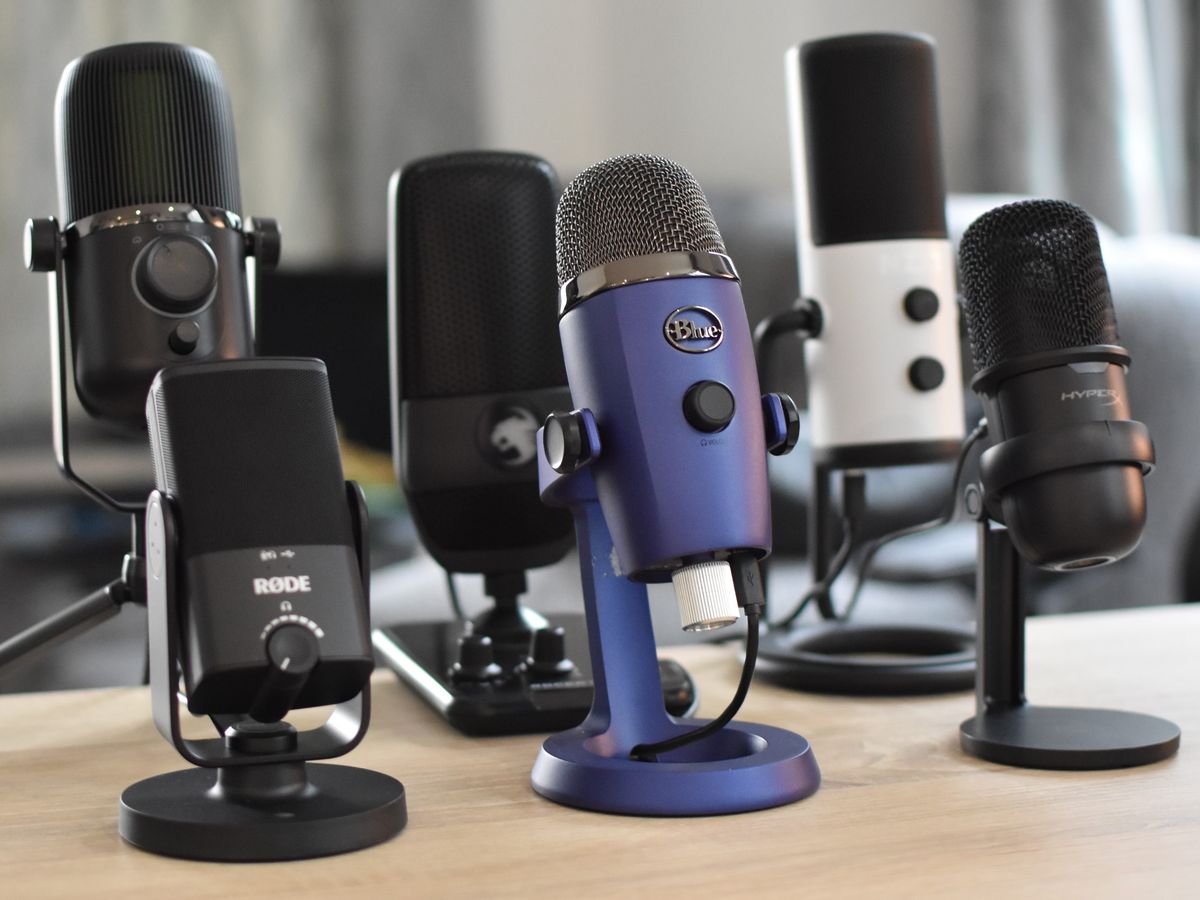
Introduction
Welcome to the world of DIY electronics! Have you ever wanted to create your own USB microphone for recording podcasts, voiceovers, or musical performances? Look no further. In this article, we will provide you with a step-by-step guide on how to make your own USB microphone from scratch.
Creating your own USB microphone can be a fun and rewarding project, allowing you to customize the microphone to suit your specific needs. Whether you are a hobbyist or a professional, this DIY project will give you a deeper understanding of the inner workings of a microphone while providing you with a great-sounding and functional device.
In the sections that follow, we will provide you with an overview of the project, the tools and materials you will need, and step-by-step instructions on building your USB microphone. We will guide you through choosing the microphone element, building the circuit, soldering the components, assembling the housing, and connecting the USB cable.
It’s important to note that this project requires some basic knowledge of electronics and soldering. If you are new to DIY electronics, don’t worry! We will explain the process in a beginner-friendly manner, making it accessible to anyone with a curious mind and a willingness to learn.
So, if you’re ready to dive into the world of DIY audio equipment, grab your soldering iron and let’s get started on making your very own USB microphone!
Overview
Before we dive into the detailed steps of making a USB microphone, let’s give you a brief overview of what this project entails. In essence, a USB microphone is a type of microphone that can be directly connected to a computer or other USB-enabled devices without the need for additional audio interfaces or preamps.
By building your own USB microphone, you have the flexibility to choose the microphone element that best suits your audio recording needs. You can select from a range of microphone elements, such as dynamic, condenser, or electret microphones, depending on the desired sound characteristics and sensitivity.
The process involves building the internal circuitry that converts the analog audio signal from the microphone element into a digital signal that can be transmitted via USB. This circuitry typically includes an analog-to-digital converter (ADC) and a USB interface.
Once the circuit is built, you will need to solder the components onto a circuit board. This step requires precision and care to ensure proper connections and avoid any short circuits.
Afterwards, you will assemble the housing for your microphone, which can be as simple or as elaborate as you desire. The housing not only protects the internal components but also contributes to the overall aesthetic of your DIY USB microphone.
Finally, you will connect a USB cable to the microphone and test it out to ensure everything is working as expected. This step may involve installing drivers or software on your computer, depending on the operating system and microphone design.
By following this step-by-step guide, you will be able to create a fully functional USB microphone that rivals commercially available options at a fraction of the cost.
Now that you have a general understanding of the process, let’s gather the necessary tools and materials to get started on your DIY USB microphone project.
Tools and Materials Needed
Before you embark on building your DIY USB microphone, make sure you have the following tools and materials ready:
- Soldering iron and solder
- Wire cutters and wire strippers
- Small screwdriver set
- Multimeter
- PCB (Printed Circuit Board) for microphone circuit
- Microphone element (dynamic, condenser, or electret)
- Analog-to-digital converter (ADC) module
- USB interface circuit module
- USB cable
- Project enclosure or housing
- Switches and buttons (if desired)
- LEDs for indicator lights (optional)
- Resistors and capacitors (as needed for the microphone circuit)
- Audio cables for internal connections
- Heat shrink tubing (to insulate soldered connections)
It’s important to note that the specific tools and materials needed may vary depending on the microphone design you choose. Some designs may require additional components or specialized tools. Therefore, it is recommended to thoroughly research and understand the requirements of your specific DIY USB microphone project before proceeding.
Additionally, having a well-organized workspace, proper ventilation, and safety equipment such as safety goggles and gloves is essential for a smooth and safe construction process.
Once you have gathered all the necessary tools and materials, you are ready to move on to the next steps of selecting the microphone element and building the circuit for your DIY USB microphone.
Step 1: Choosing a Microphone Element
The first step in building your own USB microphone is choosing the microphone element. The microphone element is the core component that captures the sound and converts it into an electrical signal.
There are several types of microphone elements available, each with its own characteristics and applications. The three common types of microphone elements used in USB microphones are dynamic, condenser, and electret microphones.
Dynamic Microphones: Dynamic microphones are known for their durability and ability to handle high sound pressure levels. They are great for live performances and recording loud sources such as drums and guitar amplifiers. These microphones do not require external power and can provide a warm and natural sound.
Condenser Microphones: Condenser microphones are known for their sensitivity and ability to capture detailed audio. They often require external power, either through batteries or phantom power from an audio interface or mixer. Condenser microphones are popular for studio recording, vocals, and capturing subtle nuances in acoustic instruments.
Electret Microphones: Electret microphones are a type of condenser microphone that incorporates a permanent charge in the diaphragm, eliminating the need for external power. They are often used in portable and consumer-grade audio devices. While electret microphones may not offer the same level of audio quality as professional-grade condenser microphones, they are still capable of delivering decent sound performance.
Consider the intended use of your USB microphone and the desired sound characteristics when selecting a microphone element. If you are unsure, you can experiment with different microphone elements to find the one that best suits your needs.
It’s important to note that different microphone elements may have different pin configurations. Be sure to carefully read the datasheet or manufacturer’s specifications to ensure compatibility with your circuit and wiring.
Once you have chosen the microphone element, you are ready to move on to the next step, which involves building the circuit for your DIY USB microphone.
Step 2: Building the Circuit
Now that you have chosen the microphone element for your DIY USB microphone, it’s time to build the circuit that will convert the analog audio signal from the microphone element into a digital signal compatible with USB.
The circuit for a USB microphone typically consists of an analog-to-digital converter (ADC) module and a USB interface circuit module. The ADC module converts the analog audio signal from the microphone element into a digital signal that can be processed by your computer or other devices. The USB interface circuit module allows the digital signal to be transmitted via USB.
First, carefully read the datasheets and instructions for both the ADC module and the USB interface circuit module. This will help you understand the pin configurations and necessary connections.
Begin by soldering the necessary components onto a printed circuit board (PCB) according to the recommended layout provided by the modules’ manufacturers. Take your time and ensure that the solder joints are clean and secure.
Next, connect the output pins of the microphone element to the input pins of the ADC module. This connection may vary depending on the specific microphone element and ADC module you are using. Refer to the datasheets for the proper pin configurations.
Similarly, connect the output pins of the ADC module to the input pins of the USB interface circuit module. Again, consult the datasheets for the correct pin connections.
It’s important to make the necessary connections with the appropriate audio cables and ensure that the connections are solid and insulated with heat shrink tubing to prevent any short circuits.
Double-check all your connections and make sure there are no loose wires or solder bridges that could cause malfunction or damage to your DIY USB microphone.
Once you have built the circuit, you are ready to move on to the next step, which involves soldering the components to ensure a solid and reliable connection.
Step 3: Soldering the Components
After successfully building the circuit for your DIY USB microphone, it’s time to solder the components to ensure a solid and reliable connection. Soldering is a critical step in the construction process, as it creates the electrical pathways and ensures proper functionality.
Start by gathering your soldering iron, solder, wire cutters, and wire strippers. Make sure your soldering iron is heated up and ready for use.
Before soldering, it’s important to clean the component leads and the PCB pads to remove any dirt or oxidation. You can lightly scrape the leads with a small knife or use a fine sandpaper to create clean surfaces for soldering.
Place the component onto the PCB, ensuring that the leads align with the corresponding pads. Use small amounts of solder to tack the component in place, making sure it is secure and will not move during the soldering process.
Now, heat the component lead and the corresponding pad on the PCB simultaneously with the soldering iron. Once the solder is heated and melted, carefully apply it to the joint. The solder should flow smoothly and create a shiny, cone-shaped fillet around the joint.
Avoid applying excessive amounts of solder, as it can create solder bridges or lead to poor connections. Remember, quality is key, so take your time and ensure each joint is clean and properly soldered.
Continue soldering each component, one by one, following the same process. Take breaks as needed to allow the soldering iron to cool down and prevent overheating.
It’s important to pay attention to the polarity of polarized components such as capacitors and diodes. Make sure you align them correctly with their corresponding pads to avoid damaging the circuit.
Once all the components are soldered, inspect the joints for any defects or cold solder joints. Cold solder joints appear dull and grainy, indicating an insufficient connection. If you find any defects, reheat the joint and apply additional solder as needed.
After soldering, let the circuit cool down and inspect it again for any potential solder bridges or short circuits. Use a multimeter to check for continuity between adjacent pads or component leads.
Once you are satisfied with the soldering and all the connections are secure, you can move on to the next step, which involves assembling the housing for your DIY USB microphone.
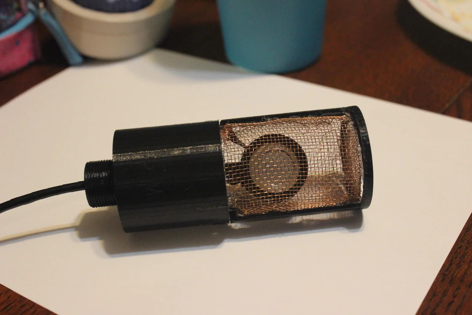
Step 4: Assembling the Housing
With the circuit for your DIY USB microphone complete, it’s time to assemble the housing that will protect and enclose the internal components. The housing not only provides physical protection but also adds to the overall aesthetics of your microphone.
First, determine the size and shape of the housing that best suits your needs. This can range from a simple cylindrical tube to a more complex custom enclosure. Consider the size of your circuit board and the additional components you may want to include, such as switches or indicator lights.
If you are using a pre-constructed enclosure, make sure it has enough space to accommodate all the components comfortably. If you are building a custom enclosure, you can use materials such as plastic, metal, or wood to create the desired shape and size.
Carefully cut openings or drill holes in the housing to accommodate switches, buttons, LEDs, and the USB cable. Use appropriate tools and techniques to ensure clean and precise cuts or holes.
Position the circuit board inside the housing, ensuring that all the components align with the openings and holes. Use screws, standoffs, or adhesive to secure the circuit board in place.
If you want to include switches or buttons, solder them onto the circuit board and position them accordingly. Make sure they are accessible from the outside of the housing for easy operation.
If desired, you can add indicator lights, such as LEDs, to provide visual feedback. Connect them to the appropriate pins on the circuit board and position them in a visible and aesthetically pleasing manner.
Once the components are in place and securely mounted, double-check all the connections to ensure everything is properly aligned and accessible.
After assembling the housing, test the functionality of the buttons, switches, and LEDs if applicable. Make sure they operate smoothly and provide the intended feedback.
Finally, secure the housing by closing or attaching any covers or panels. Ensure that the USB cable is properly routed through the hole and securely connected to the circuit board.
With the housing assembled, your DIY USB microphone is taking shape. In the next step, we will guide you through connecting the USB cable and finalizing the construction of your microphone.
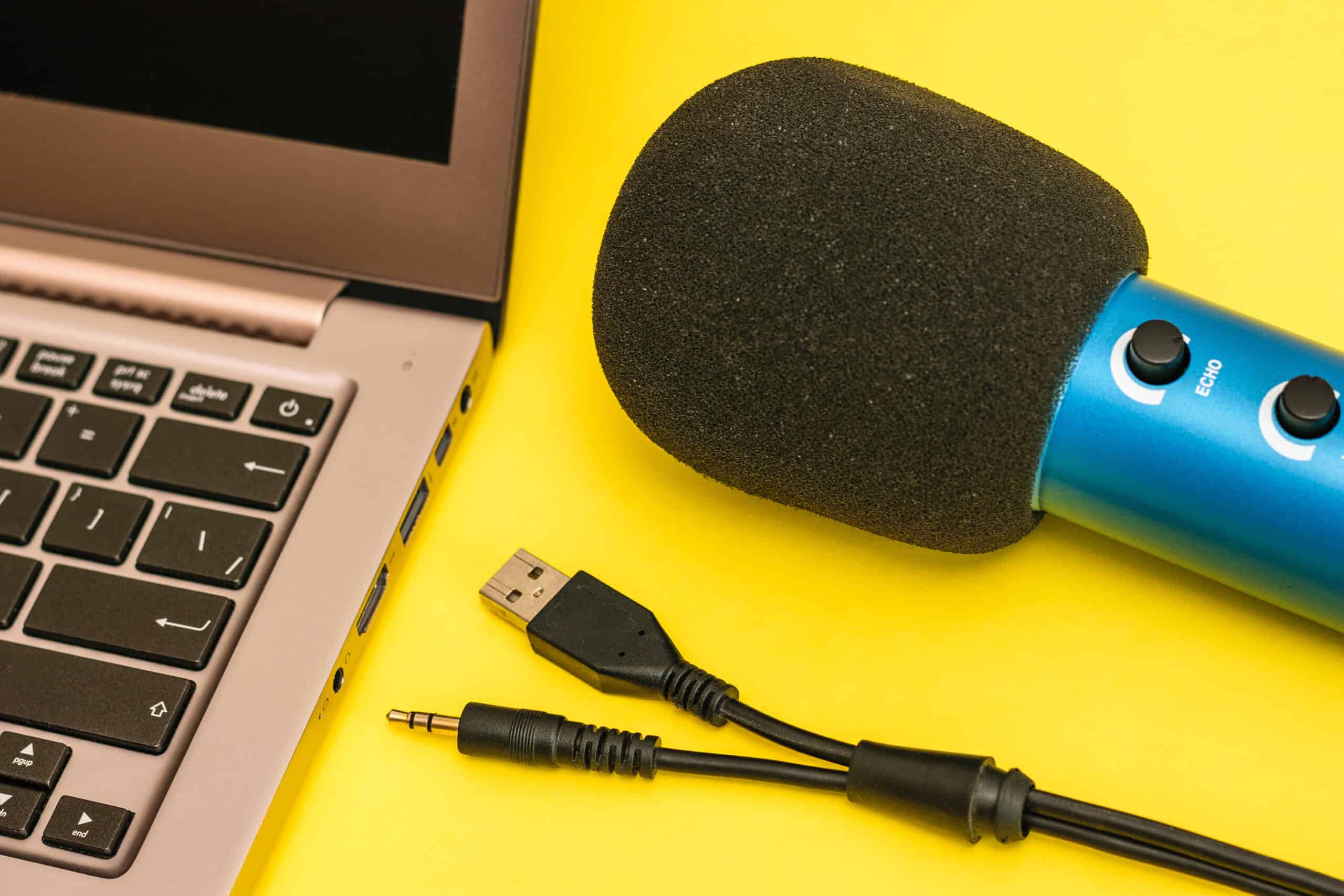
Step 5: Connecting the USB Cable
Now that you have successfully assembled the housing for your DIY USB microphone, it’s time to connect the USB cable. This step is crucial as it allows the digital audio signal to be transmitted from your microphone to your computer or other USB-enabled devices.
First, determine the appropriate location on the housing to position the USB connector. This should be easily accessible and allow for a secure connection.
Next, strip the outer insulation of the USB cable carefully using wire strippers. This will expose the four wires inside: red for power, black for ground, and white and green for data transfer.
Strip a small portion of the insulation from each individual wire, making sure not to expose too much. This will give you enough room to solder the wires to the appropriate points on the circuit board.
Refer to the pinout diagram or datasheet of your USB interface circuit module to identify the correct points to solder the wires. Typically, the red wire connects to VCC, the black wire to GND, and the white and green wires to the data+ and data- pins.
Solder each wire carefully and securely to its corresponding point on the circuit board. Ensure that there are no loose connections or solder bridges between the wires.
Once the soldering is complete, reinforce the connections by using heat shrink tubing or electrical tape to insulate the soldered area. This will protect the connections from any potential short circuits or damage.
After the connections are insulated, route the USB cable through the designated hole in the housing and securely attach the USB connector to the housing. This can be done by screwing it in place or using adhesive or other suitable methods.
Double-check all the connections to ensure they are secure and properly insulated. Verify the alignment of the USB connector and make sure it is securely attached to the housing.
With the USB cable connected, your DIY USB microphone is almost complete. In the next step, we will guide you through testing the microphone to ensure it is functioning correctly.
Step 6: Testing the USB Microphone
Now that you have completed the construction of your DIY USB microphone, it’s time to put it to the test. Testing is an essential step to ensure that your microphone is functioning correctly and delivering the desired audio quality.
Start by connecting your microphone to your computer or USB-enabled device using the USB cable. Make sure the cable is securely plugged into both the microphone and the device.
Once connected, you may need to install drivers or software depending on your operating system and the specific design of your microphone. Check the manufacturer’s instructions or website for any necessary software or driver downloads.
Open your preferred audio recording software or app on your computer. Select the input device as your USB microphone. Make sure the microphone is recognized by your computer and that the input levels are properly set.
To test the microphone, speak or make sounds into it. Check the audio levels in your recording software to ensure that the microphone is capturing sound. Adjust the input levels as needed to achieve optimal audio quality without any distortion or clipping.
Listen to the recorded sound to assess the quality and clarity. Test different recording scenarios to evaluate the microphone’s performance in various conditions, such as different distances and volume levels.
If you encounter any issues with the microphone, double-check all the connections, ensure the drivers or software are properly installed, and verify the settings in your computer’s audio preferences.
If the microphone is not functioning correctly, consult troubleshooting resources or seek guidance from online communities or forums specializing in DIY electronics.
Once you are satisfied with the performance of your DIY USB microphone, you can proceed to use it for various applications such as recording podcasts, voiceovers, musical performances, or any other creative endeavors that require high-quality audio capture.
Remember to keep your microphone well-maintained and handle it with care to ensure its longevity and continued performance.
Congratulations! You have successfully built and tested your own USB microphone. Enjoy the satisfaction of knowing that you have created a functional and unique audio recording tool!
Conclusion
Building your own USB microphone is a rewarding and fulfilling project that allows you to customize your audio recording setup to suit your needs. By following the step-by-step guide in this article, you have learned how to choose a microphone element, build the circuit, solder the components, assemble the housing, connect the USB cable, and test the microphone.
Throughout this DIY journey, you have gained valuable knowledge of electronics, soldering techniques, and audio engineering principles. You have also developed a deeper understanding of the inner workings of a USB microphone and the process of converting analog audio into digital signals.
Your DIY USB microphone offers you the flexibility to tailor its sound characteristics to your preferences, whether you’re looking for a warm and vintage tone or a crisp and modern sound. Additionally, you have the satisfaction of knowing that you have created a functional piece of audio equipment that rivals commercially available options at a fraction of the cost.
Remember that this project requires some basic knowledge of electronics and soldering. If you’re new to DIY electronics, take the time to research, practice, and familiarize yourself with the necessary tools and techniques. As you gain more experience, you can explore advanced modifications and customization options to further refine your microphone.
Now that you have completed your DIY USB microphone, it’s time to unleash your creativity and put it to use! Whether you’re recording podcasts, narrating videos, or capturing the perfect vocal performance, your DIY USB microphone is ready to help you achieve professional-quality audio.
Enjoy the journey of exploring the endless possibilities of audio recording with your DIY USB microphone. Let your passion for sound fuel your creativity and drive your projects to new heights.
Happy recording!