Introduction
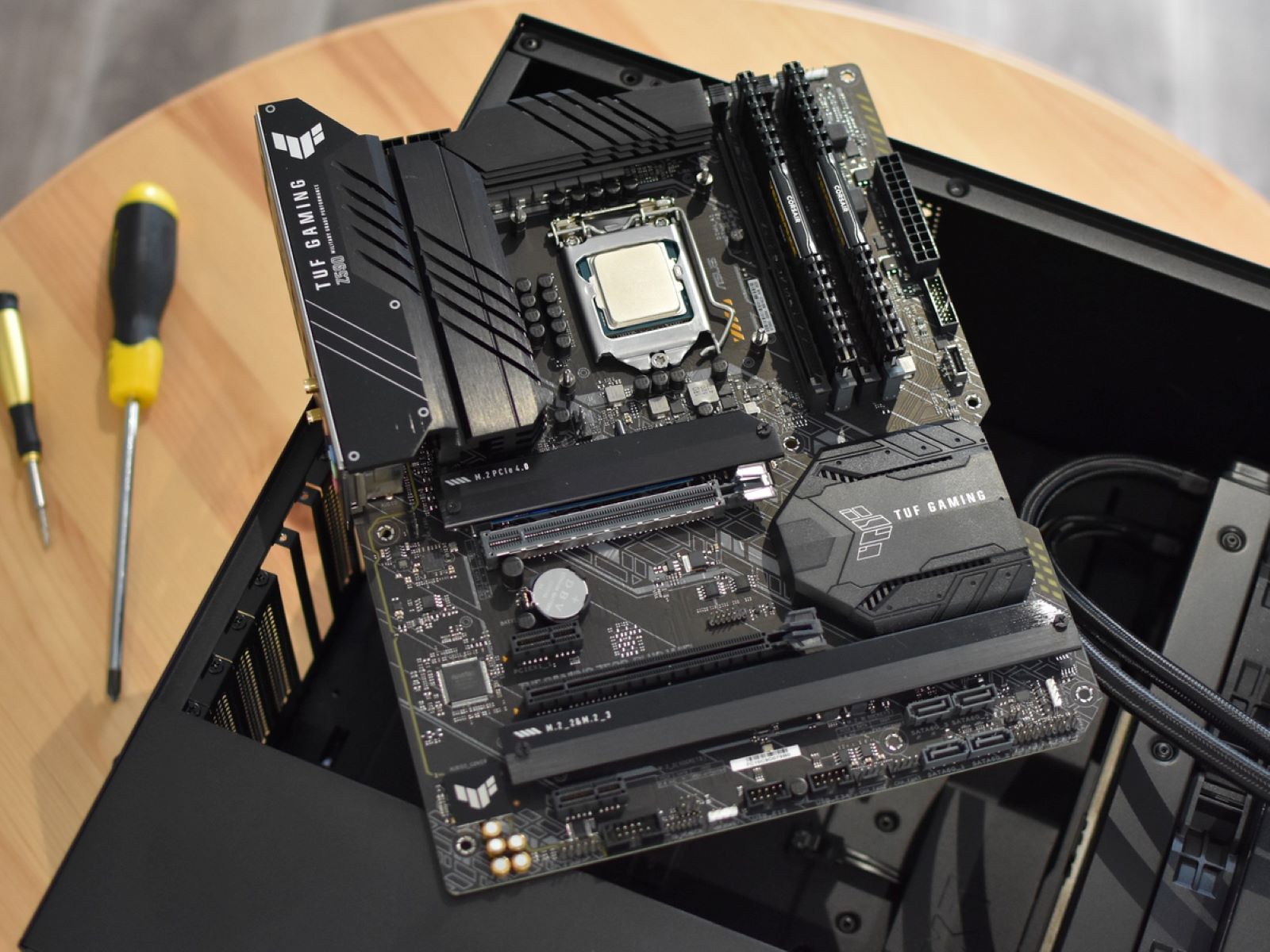
When building or upgrading a computer, one crucial step is connecting the front panel connectors to the motherboard. These connectors allow you to operate various functions of your computer’s case, such as the power button, reset switch, LEDs, USB ports, and audio jacks. While this may seem like a daunting task for beginners, it is actually a straightforward process that can be accomplished with a little patience and understanding.
In this guide, we will walk you through the steps to connect the front panel connectors to the motherboard. We will explain the purpose of each connector and provide you with the necessary information to ensure a successful connection. Whether you are building a new computer from scratch or replacing a faulty connector, this guide will help you get your front panel working seamlessly.
Understanding the front panel connectors is crucial before you begin the connection process. These connectors consist of small cables with individual pins, each serving a specific function. Some of the key connectors you will come across include the power button, reset switch, power LED, HDD LED, speaker, USB ports, and audio jacks. Properly connecting these components ensures that your computer’s front panel functions as intended, allowing you to power on/off the system, reset it, and access external devices and audio peripherals.
Before we dive into the connection process itself, it is important to have the necessary tools and equipment at hand. You will need a screwdriver, preferably with a magnetic tip, to secure the connectors to the motherboard. Additionally, having the motherboard manual or documentation readily available is essential, as it provides specific instructions on the layout and pin connections for your specific motherboard model. With these tools and resources ready, you can now move on to the next step of identifying the front panel connectors.
Understanding the Front Panel Connectors
Before you start connecting the front panel connectors to your motherboard, it’s important to have a good understanding of what each connector does. This knowledge will help you make the correct connections and ensure that everything functions properly.
Here are the main front panel connectors you should be familiar with:
- Power button: This connector is responsible for turning your computer on and off. When you press the power button on your computer case, it sends a signal through this connector to the motherboard, initiating the power supply to start.
- Reset switch: The reset switch is used to restart your computer. By pressing this button, you can perform a soft reset, which reboots the system without cutting off the power completely.
- Power LED: This connector controls the LED light on your computer case that indicates whether the system is powered on or off. It is typically a two-pin connector with polarity, meaning it needs to be inserted correctly to function properly.
- HDD LED: The HDD LED connector is responsible for indicating hard drive activity. It blinks or remains lit when the hard drive is being accessed, providing visual feedback on its status.
- Speaker: The speaker connector allows your computer to produce audible beeping sounds. These beeps are often used as error code indicators during the boot process, helping you diagnose any hardware or software issues that may arise.
- USB ports: These connectors allow you to connect USB devices, such as keyboards, mice, and external storage devices, directly to the front of your computer case.
- Audio jacks: The audio jacks are used for connecting headphones, microphones, speakers, or other audio devices to the front panel of your computer.
Understanding the functions of these connectors will help you make the correct connections to the motherboard. Additionally, consult your motherboard manual for specific pin configurations and labeling to ensure accurate placement of the connectors.
Now that you have a clear understanding of the front panel connectors, it’s time to move on to the next step: identifying the connectors on your specific motherboard model.
Tools and Equipment Needed
Before you start connecting the front panel connectors to your motherboard, it’s important to gather all the necessary tools and equipment. Having the right tools will make the process easier and help ensure a successful connection.
Here are the essential tools and equipment you’ll need:
- Screwdriver: A screwdriver is required to secure the connectors to the motherboard. It’s recommended to use a screwdriver with a magnetic tip to prevent losing screws in hard-to-reach places.
- Motherboard manual or documentation: Your motherboard manual or documentation is an invaluable resource for this process. It provides detailed instructions on the layout and pin configurations specific to your motherboard model. Make sure to have it readily available to reference throughout the connection process.
Having these tools and equipment prepared beforehand will save you time and eliminate the need for interruptions during the connection process. Make sure to have them within reach before you begin.
With the appropriate tools in hand, you’re now ready to move on to the next step: identifying the front panel connectors on your motherboard.
Step 1: Identify the Front Panel Connectors
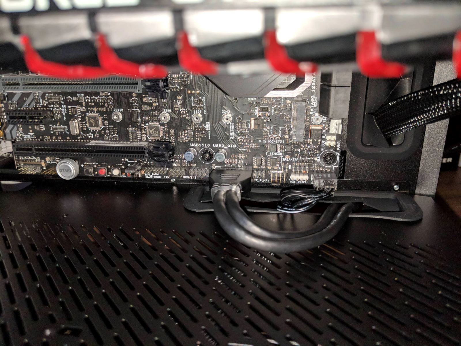
Before you can start connecting the front panel connectors to your motherboard, you’ll need to identify them. The front panel connectors are typically located on the bottom-right corner of the motherboard, near the edge. They are labeled with abbreviations or symbols that indicate their specific function.
To identify the front panel connectors, follow these steps:
- Refer to your motherboard’s manual: Your motherboard’s manual is the best resource for identifying the front panel connectors. It will provide a diagram or detailed description of the connectors, their locations on the motherboard, and their corresponding functions. If you don’t have the physical manual, check the manufacturer’s website for a digital version.
- Look for labels or markings: The connectors on the motherboard are often labeled or marked with abbreviations that indicate their purpose. Common labels you may find include “PWR SW” for the power button, “RST SW” for the reset switch, “PWR LED” for the power LED, “HDD LED” for the hard drive activity LED, and “SPK” for the speaker connector.
- Take note of the pin configuration: Each front panel connector consists of pins, and it’s essential to understand the pin configuration. Most connectors have polarity, meaning they need to be inserted in a specific orientation. The motherboard manual will provide information on the pin layout and any polarity requirements.
- Double-check your findings: Once you have identified the front panel connectors and their locations, double-check your findings. Make sure you have correctly identified each connector, and cross-reference them with the motherboard manual to confirm their functions.
By following these steps, you will have a clear understanding of the front panel connectors on your motherboard and be ready to proceed with the connection process. It’s important to be thorough in your identification to ensure a successful and hassle-free connection process.
Step 2: Refer to the Motherboard Manual
With the front panel connectors identified, the next step is to refer to the motherboard manual for specific instructions on how to connect them. The motherboard manual provides the necessary guidance to ensure accurate and successful connections.
Follow these steps when referring to the motherboard manual:
- Consult the manual: Locate the section in the manual that covers the front panel connectors. This section is typically found in the “Hardware Installation” or “Connections” chapter. If you are using a digital version of the manual, use the search function to quickly find the relevant information.
- Study the diagram: The manual will include a diagram or labeled illustration of the motherboard with the front panel connectors and their corresponding locations. Take the time to study the diagram and familiarize yourself with the layout.
- Note the pin configuration: The manual will provide detailed information about the pin configuration for each front panel connector. This includes the number of pins, their layout, and any polarity requirements. Pay close attention to this information as it is crucial for accurate connections.
- Follow the instructions: The manual will provide step-by-step instructions on how to connect each front panel connector. It may include specific illustrations or descriptions to guide you through the process. Carefully follow these instructions to ensure proper connections.
- Take note of any additional instructions: The motherboard manual may contain additional instructions or considerations specific to your motherboard model. Make sure to read and understand any supplemental information provided.
By referring to the motherboard manual, you ensure that you have the correct information and instructions for connecting the front panel connectors. Following the manual’s guidance will help you make accurate connections and avoid any potential issues that may arise from incorrect installations.
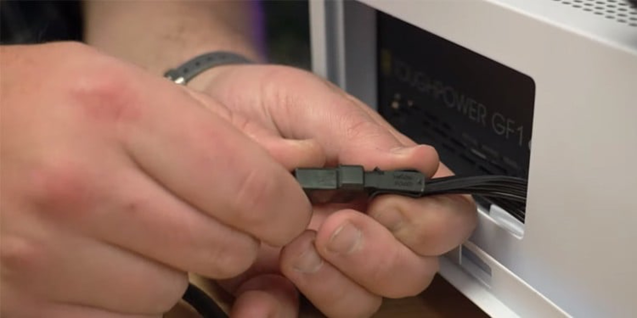
Step 3: Connect the Power Button and Reset Switch
Connecting the power button and reset switch is an important step in the process of connecting the front panel connectors to your motherboard. These connectors allow you to control the power and reset functions of your computer case.
Follow these steps to connect the power button and reset switch:
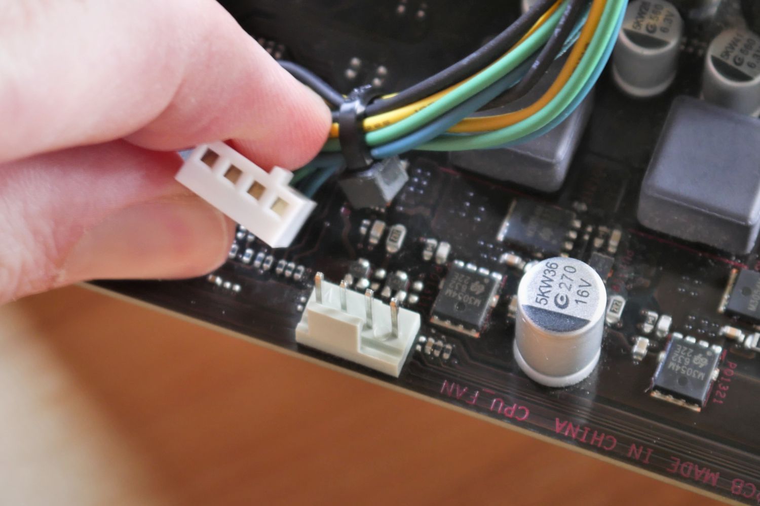
- Locate the power button connector: Identify the two-pin power button connector on your motherboard. It is labeled as “PWR BTN” or something similar in the motherboard manual and is usually located near the front panel header where the front panel connectors are grouped.
- Connect the power button: Take the two-pin power button connector and align it with the corresponding pins on the motherboard. Ensure that the connector is oriented correctly; one pin usually has a positive (+) symbol or is marked with a colored wire. Gently push the connector onto the pins until it is firmly seated.
- Locate the reset switch connector: Similarly, locate the reset switch connector on your motherboard. It is labeled as “RST SW” or similar in the motherboard manual and is typically positioned near the power button connector.
- Connect the reset switch: Take the two-pin reset switch connector and align it with the appropriate pins on the motherboard. Again, check the orientation of the connector, noting any positive (+) symbols or colored wires. Insert the connector onto the pins, ensuring a secure connection.
After connecting the power button and reset switch, double-check the connections to ensure they are secure. It’s important to note that polarity is usually not a concern for these connectors, as they are simple momentary switches that complete a circuit when pressed.
Once you have successfully connected the power button and reset switch, you can proceed to the next step: connecting the power LED.
Step 4: Connect the Power LED
Connecting the power LED is an essential step in the process of connecting the front panel connectors to your motherboard. The power LED provides visual feedback on the status of your computer’s power.
Follow these steps to connect the power LED:
- Locate the power LED connector: Identify the two-pin power LED connector on your motherboard. It is often labeled as “PWR LED” or similar in the motherboard manual. Look for the corresponding pins near the front panel header where the other connectors are located.
- Determine the polarity: The power LED connector typically has polarity, meaning it needs to be inserted correctly for it to function. Note the colored wires or the positive (+) symbol on one of the pins of the connector.
- Connect the power LED: Take the two-pin power LED connector and align it with the designated pins on the motherboard. Ensure that you match the positive (+) wire or colored wire with the appropriate pin that indicates positive polarity. Gently push the connector onto the pins until it is securely attached.
It’s important to double-check the connection after inserting the power LED connector to ensure it is securely attached. A loose connection may cause the LED not to function properly.
After successfully connecting the power LED, you can move on to the next step: connecting the HDD LED.
Step 5: Connect the HDD LED
Connecting the HDD (hard disk drive) LED is an important step in the process of connecting the front panel connectors to your motherboard. The HDD LED provides visual feedback on the activity of your computer’s hard drive.
Follow these steps to connect the HDD LED:
- Locate the HDD LED connector: Identify the two-pin HDD LED connector on your motherboard. It is usually labeled as “HDD LED” or similar in the motherboard manual. Look for the corresponding pins near the front panel header where the other connectors are positioned.
- Determine the polarity: The HDD LED connector typically has polarity, which means it needs to be inserted correctly for it to function properly. Observe the colored wires or the positive (+) symbol on one of the pins of the connector.
- Connect the HDD LED: Take the two-pin HDD LED connector and align it with the designated pins on the motherboard. Ensure that you match the positive (+) wire or colored wire with the appropriate pin indicating positive polarity. Firmly press the connector onto the pins until it is securely attached.
After connecting the HDD LED, it’s crucial to double-check the connection to ensure it is firmly attached. A loose connection may result in the LED not functioning correctly or providing inaccurate feedback on the hard drive’s activity.
Once you have successfully connected the HDD LED, you can proceed to the next step: connecting the speaker.
Step 6: Connect the Speaker
Connecting the speaker is a vital step in the process of connecting the front panel connectors to your motherboard. The speaker allows your computer to produce audible alerts and error codes, aiding in the diagnosis of hardware or software issues.
Follow these steps to connect the speaker:
- Locate the speaker connector: Identify the two-pin speaker connector on your motherboard. It is typically labeled as “SPK” or similar in the motherboard manual. Look for the corresponding pins near the front panel header or audio connectors.
- Connect the speaker: Take the two-pin speaker connector and align it with the designated pins on the motherboard. Ensure that you insert the connector correctly, matching the polarity if specified. Gently push the connector onto the pins until it is firmly attached.
After connecting the speaker, double-check the connection to ensure that it is secure. A loose connection may result in distorted or no sound output from the speaker.
It’s important to note that not all motherboards have a built-in speaker connector. In such cases, you may need to purchase a separate speaker that connects to the appropriate audio headers on the motherboard.
Once you have successfully connected the speaker, you can proceed to the next step: connecting the USB ports and audio jacks.
Step 7: Connect the USB Ports and Audio Jacks
Connecting the USB ports and audio jacks is a crucial step in the process of connecting the front panel connectors to your motherboard. These connectors allow you to conveniently access USB devices and audio peripherals from the front of your computer case.
Follow these steps to connect the USB ports and audio jacks:
- Locate the USB and audio connectors: Identify the USB and audio connectors on your motherboard. The USB connectors are usually labeled as “USB” or “USB 2.0” while the audio connectors are labeled as “HD Audio” or similar, in the motherboard manual. Look for the corresponding headers near the front panel or audio connectors.
- Connect the USB ports: Take the USB connector cable from the front panel of your computer case and locate the corresponding USB headers on the motherboard. Align the connector with the pins, ensuring that you match the orientation of the connector correctly. Gently push the connector onto the pins until it is securely attached.
- Connect the audio jacks: Take the audio connector cable from the front panel of your computer case and locate the corresponding audio headers on the motherboard. Align the connector with the pins, making sure to match the orientation correctly. Gently push the connector onto the pins until it is firmly attached.
After connecting the USB ports and audio jacks, it’s important to double-check the connections to ensure they are secure. Loose connections may result in the USB ports or audio jacks not functioning correctly.
It’s worth noting that some motherboards may have additional headers for USB 3.0 or other audio configurations. Consult your motherboard manual for specific instructions on how to connect these connectors if they are available.
Once you have successfully connected the USB ports and audio jacks, you can proceed to the next step: double-checking all the connections before powering on your computer.
Step 8: Double-Check the Connections
Before powering on your computer, it’s crucial to double-check all the connections you made for the front panel connectors. Verifying the connections ensures that everything is properly aligned and securely attached, minimizing the risk of any issues during operation.
Follow these steps to double-check the connections:
- Visually inspect the connections: Take a close look at each connector and its corresponding pins on the motherboard. Ensure that the connectors are fully seated on the pins and that there are no loose or misaligned connections.
- Check for proper orientation: Verify that the connectors are inserted with the correct polarity, if applicable. Look for any positive (+) symbols, colored wires, or other indicators that denote the correct orientation.
- Ensure tightness: Gently wiggle each connector to ensure they are securely attached. A loose connection may cause intermittent functionality or disruption in the performance of the front panel components.
- Refer to the motherboard manual: If you are uncertain about any of the connections, consult the motherboard manual once again. Cross-check the pin configurations and connector labels to ensure that everything is connected correctly.
Double-checking the connections provides peace of mind and reduces the potential for problems arising from loose or incorrect connections. It’s a crucial step before proceeding to power on your computer.
Once you are confident that all the connections are secure and accurate, you are ready to power on your computer. Press the power button and observe the front panel components to ensure they are functioning as intended.
Congratulations! You have successfully connected the front panel connectors to your motherboard. Enjoy the seamless operation of your computer, powered by the correct connection of these essential components.
Conclusion
Connecting the front panel connectors to your motherboard is a crucial step in the process of building or upgrading your computer. By understanding the purpose of each connector and following the step-by-step instructions outlined in this guide, you can ensure a smooth and successful connection process.
Throughout this guide, you have learned how to identify the front panel connectors, refer to the motherboard manual, and connect various components such as the power button, reset switch, power LED, HDD LED, speaker, USB ports, and audio jacks.
Remember to use the appropriate tools, such as a screwdriver, and consult your motherboard manual for accurate pin configurations and instructions specific to your motherboard model.
By double-checking each connection and ensuring their proper alignment, polarity (if applicable), and security, you minimize the risk of any issues during operation and enhance the functionality of your computer’s front panel.
With the front panel connectors successfully connected, you’re now ready to power on your computer and enjoy its full range of features and capabilities.
Should you need to troubleshoot any issues related to the front panel connectors in the future, consult the motherboard manual and recheck the connections to ensure they are still secure and correct.
Remember, the front panel connectors play a crucial role in the overall functionality of your computer, providing convenient access to essential functions and peripherals. Taking the time to properly connect them ensures a smooth and seamless computing experience.
Now that you have successfully connected the front panel connectors, it’s time to power on your computer and dive into your favorite applications and tasks with confidence!