Introduction
Connecting a PC case plug to the motherboard is an essential step in building a computer. The front panel connectors on the PC case allow you to connect various components, such as the power switch, reset switch, power LED, HDD LED, audio jacks, and USB ports, to the motherboard.
Properly connecting these plugs ensures that all the front panel features of your computer case work seamlessly. However, for beginner PC builders, this process can seem a bit daunting. But fear not! In this guide, we will walk you through the step-by-step process of connecting a PC case plug to the motherboard.
Before we begin, it’s important to note that the connectors and their placement can vary depending on the motherboard and PC case model. Therefore, it’s always a good idea to consult the user manuals for both the motherboard and the PC case to ensure you are connecting the plugs correctly.
In the following sections, we will identify the necessary tools and materials, guide you through each step of the connection process, and provide useful tips along the way. By the end of this guide, you will have the knowledge and confidence to connect the PC case plug to your motherboard like a pro.
So, without further ado, let’s jump right into it and get started with the first step: identifying the front panel connectors on your PC case!
Required Tools and Materials
Before you begin connecting the PC case plug to the motherboard, you will need to gather a few tools and materials. Having these items ready will ensure a smooth and efficient process. Here are the essential tools and materials you’ll need:
- A screwdriver (usually a Phillips-head or flathead screwdriver) – This will be used to open the PC case and secure the connectors.
- The motherboard manual – This manual provides detailed instructions on the layout and placement of the various connectors on the motherboard.
- The PC case manual – This manual contains information specific to your PC case, including the location and pin configuration of the front panel connectors.
- An anti-static wristband (optional but recommended) – This helps protect your components from static electricity damage while working inside the computer case.
- A well-lit workspace – It’s important to have good lighting to easily see the connectors and ensure proper placement.
In addition to these tools and materials, it’s crucial to ensure that both the motherboard and the PC case are compatible. This means checking if they have the same connector type (most commonly ATX or Micro-ATX) and the same pin configuration for the front panel connectors. Having a clear understanding of these compatibility factors will save you time and frustration during the assembly process.
Now that you have all the necessary tools and materials gathered, you’re ready to move on to the next step: identifying the front panel connectors on your PC case.
Step 1: Identify the Front Panel Connectors
Before you can connect the PC case plug to the motherboard, it’s important to identify and familiarize yourself with the front panel connectors on your PC case. These connectors are responsible for connecting various components, such as the power switch, reset switch, power LED, HDD LED, audio jacks, and USB ports, to the motherboard.
The location and arrangement of these connectors may vary depending on your PC case model. However, they are typically located on the front or top edge of the motherboard. To find them, you can refer to the PC case manual or look for labeled pins or headers near the bottom right corner of the motherboard.
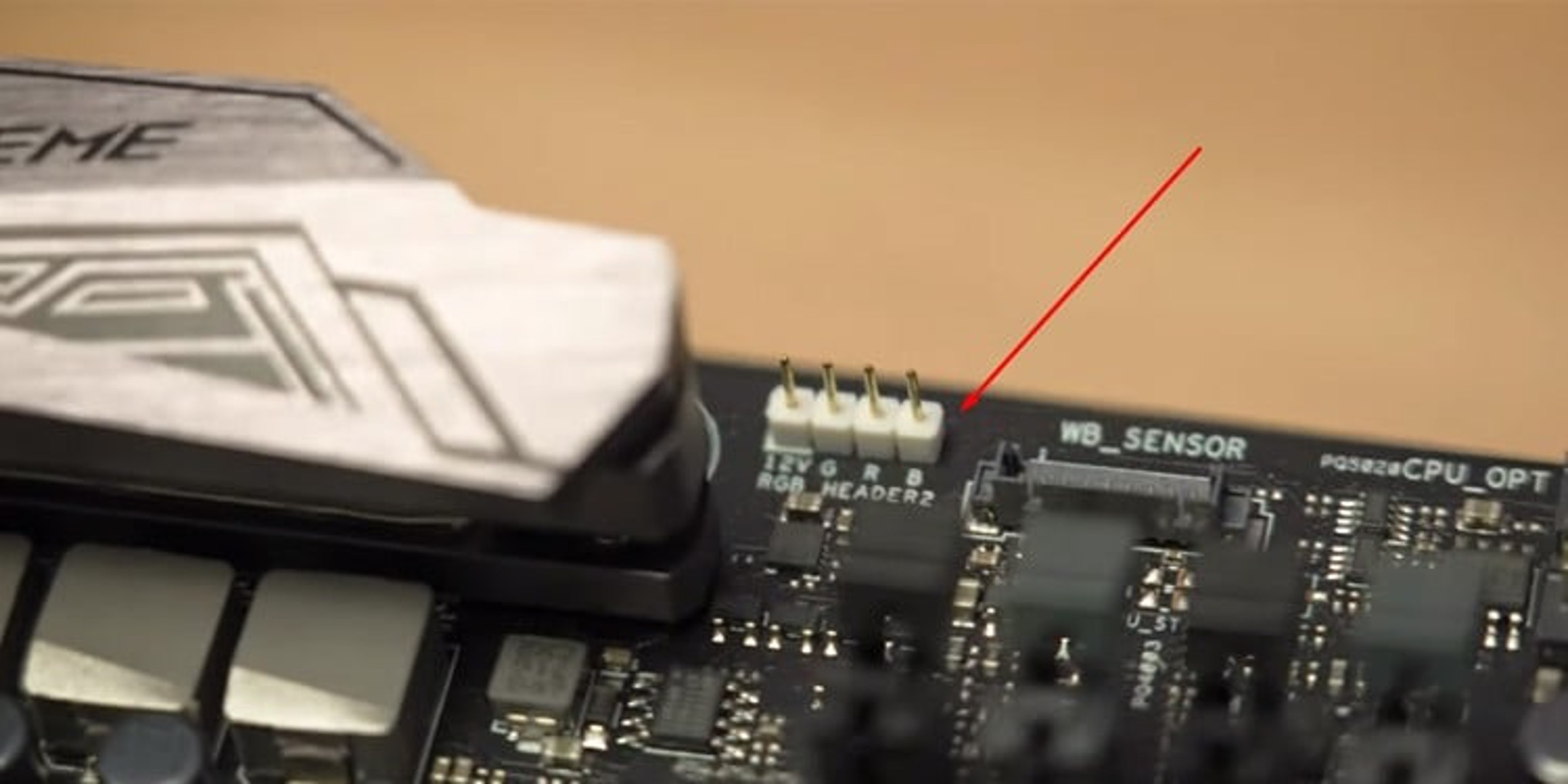
Typically, the front panel connectors are labeled with abbreviations such as “PWRSW” for the power switch, “RSTSW” for the reset switch, “PWRLED” for the power LED, “HDLED” for the HDD LED, “AUD” for the audio jack, and “USB” for the USB ports. Some PC cases may also include additional connectors for features like fan controllers or RGB lighting.
Take a moment to carefully examine the front panel connectors and their labels. It’s helpful to make a note of their location and orientation, as this will come in handy when connecting them to the motherboard in the following steps.
If you’re unsure about the labeling or orientation of the connectors, don’t worry. The motherboard manual will provide detailed information on the layout and pin configuration of these connectors. Refer to the manual to ensure you are connecting the plugs correctly.
Now that you have identified the front panel connectors on your PC case, you’re ready to move on to the next step: preparing the motherboard for connection.
Step 2: Prepare the Motherboard
Now that you have identified the front panel connectors on your PC case, the next step is to prepare the motherboard for connection. This involves locating the corresponding pins or headers on the motherboard and ensuring they are ready for the front panel plug connections.
First, consult the motherboard manual to find the exact location of the front panel pins or headers. These are typically located near the bottom right corner of the motherboard. The manual will provide a diagram or description of the pin layout, making it easy for you to identify the correct positions.
Next, gently open the motherboard tray on your PC case. This will provide access to the rear side of the motherboard, where the connectors are located. It’s important to handle the motherboard with care and avoid touching any delicate components, such as the CPU or memory modules.
Once you have access to the rear side of the motherboard, locate the front panel pins or headers. They will be labeled on the motherboard with abbreviations or symbols that correspond to the front panel connectors, such as “PWR_SW” for the power switch, “RST_SW” for the reset switch, and so on. Take note of their positioning and orientation.
If your motherboard has individual pins, you may need to remove any plastic jumpers or protective covers from them before inserting the front panel connectors. Use caution while handling these pins to avoid bending or damaging them.
If your motherboard has headers, these are usually labeled with the corresponding front panel connector names. Ensure that any protective covers on the headers are removed before proceeding.
With the motherboard prepared and the front panel pin or header locations identified, you’re now ready to move on to the next step: inserting the front panel connectors into the motherboard.
Step 3: Insert the Front Panel Connectors
Now that you have prepared the motherboard, it’s time to connect the front panel connectors from the PC case. Follow these steps to correctly insert the front panel connectors:
- Refer to the PC case manual or the labels on the connectors to identify each front panel connector.
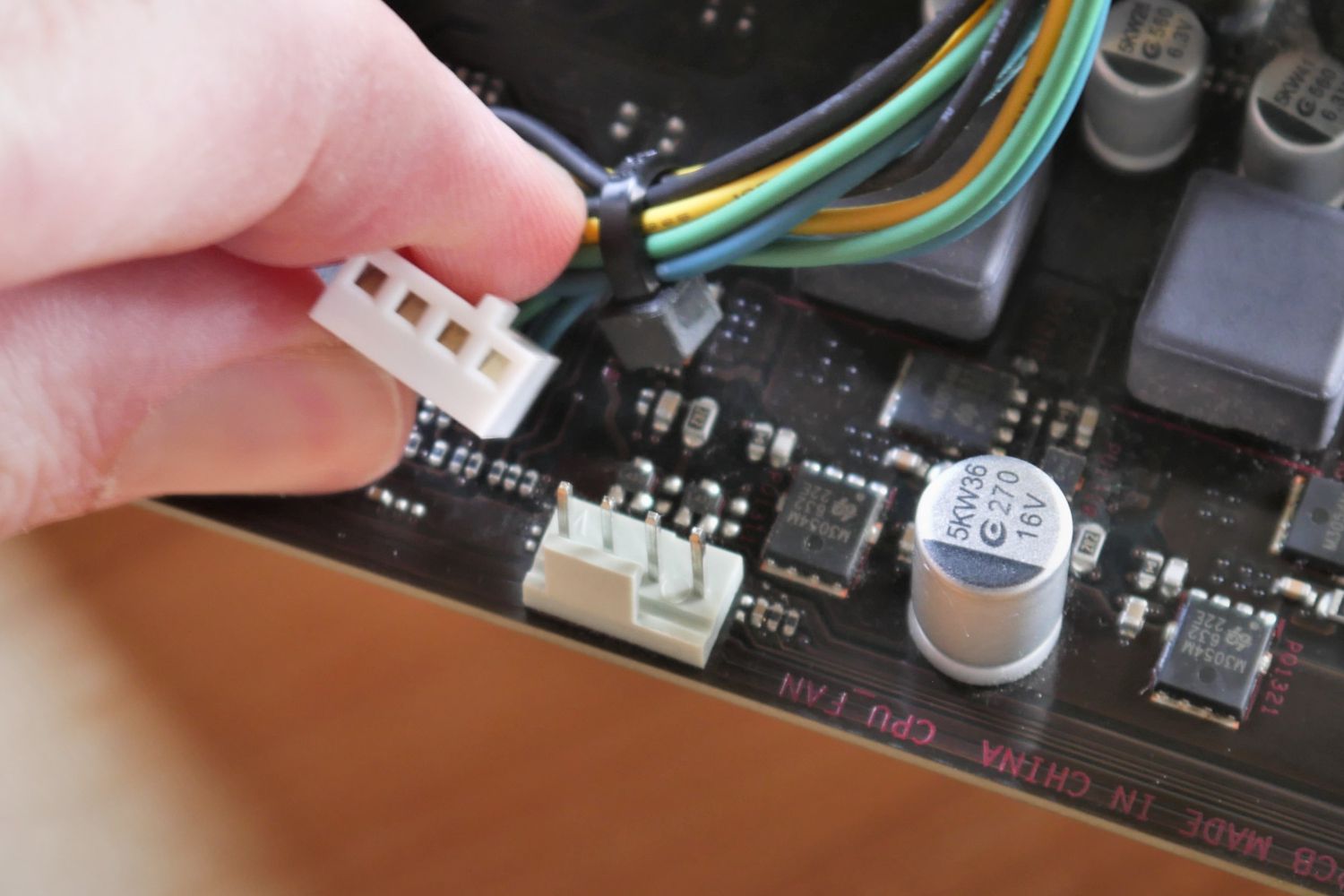
- Take the power switch connector and align it with the corresponding pins or header on the motherboard. Ensure that the orientation of the connector matches the pins.
- Gently insert the power switch connector onto the pins or into the header. Apply light pressure until it is securely attached. Do not force it or use excessive pressure.
- Repeat the process for each front panel connector, including the reset switch, power LED, HDD LED, audio jacks, and any additional connectors your PC case may have.
- Ensure that each connector is firmly attached and seated correctly on the appropriate pins or headers.
- Double-check the orientation of each connector to make sure they are all aligned correctly. Improperly connected connectors may cause components to malfunction.
It’s important to handle the connectors with care during this step. Be gentle and avoid bending any pins or damaging the connectors or motherboard.
If you encounter difficulty inserting the connectors, double-check the orientation and alignment. In some cases, you may need to rotate the connector by 180 degrees to properly align it with the pins or header.
Once all the front panel connectors are properly inserted and secured onto the motherboard, you can proceed to the next step: connecting the power switch.
Step 4: Connect the Power Switch
Connecting the power switch is a crucial step in the process of connecting the PC case plug to the motherboard. The power switch allows you to turn your computer on and off. Follow these steps to connect the power switch:
- Locate the power switch connector on your PC case. It is usually labeled as “PWRSW” or “PWR_BTN.”
- Refer to the motherboard manual to find the corresponding pins or headers for the power switch connection. These are typically labeled as “PWR_SW” or “Power.”
- Take the power switch connector and align it with the power switch pins or header on the motherboard.
- Gently push or slide the power switch connector onto the pins or insert it into the header, ensuring that it is securely attached.
- Double-check the orientation of the connector to make sure it is aligned correctly. The power switch should be connected with the positive and negative terminals aligned properly.
Once the power switch is connected, gently tuck the excess cable out of the way to prevent any interference with other components or airflow within the case.
It is important to note that some PC cases may have separate connections for power and reset switches, while others may have a combined connector. Refer to your PC case and motherboard manuals to ensure you connect the power switch correctly.
With the power switch successfully connected, you’re one step closer to completing the connection of the PC case plug to the motherboard. Proceed to the next step: connecting the reset switch.
Step 5: Connect the Reset Switch
The reset switch is responsible for resetting your computer in case it becomes unresponsive or freezes. Follow these steps to correctly connect the reset switch:
- Locate the reset switch connector on your PC case. It is often labeled as “RSTSW” or “RESET.”
- Refer to the motherboard manual to find the corresponding pins or headers for the reset switch connection. These are typically labeled as “RST_SW” or “Reset.”
- Take the reset switch connector and align it with the reset switch pins or header on the motherboard.
- Gently push or slide the reset switch connector onto the pins or insert it into the header, ensuring that it is securely attached.
- Double-check the orientation of the connector to make sure it is aligned correctly. The reset switch should be connected with the positive and negative terminals aligned properly.
Once the reset switch is connected, make sure the excess cable is neatly tucked away to prevent any interference with other components or airflow within the case.
It’s important to note that not all PC cases come with a reset switch. If your PC case does not have one, you can skip this step and proceed to the next step.
With the power switch and reset switch successfully connected, your front panel connectors are taking shape. In the next step, we will move on to connecting the power LED.
Step 6: Connect the Power LED
The power LED (Light Emitting Diode) on your PC case indicates whether your computer is powered on or off. Connecting the power LED correctly is crucial for proper functionality and visual feedback. Follow these steps to connect the power LED:
- Locate the power LED connector on your PC case. It is typically labeled as “PWRLED” or “POWER_LED.”
- Refer to the motherboard manual to find the corresponding pins or headers for the power LED connection. They are usually labeled as “PWR_LED” or “Power LED.”
- Take the power LED connector and align it with the power LED pins or header on the motherboard.
- Gently push or slide the power LED connector onto the pins or insert it into the header, ensuring that it is securely attached.
- Double-check the orientation of the connector to make sure it is aligned correctly. The power LED should be connected with the positive and negative terminals properly aligned.
Once the power LED is connected, you can test it by turning on your computer. The power LED should now light up, indicating that your computer is powered on.
If the power LED does not light up after connecting, double-check the orientation and placement of the connector. Sometimes, flipping the connection around 180 degrees can resolve the issue.
Remember to neatly manage the excess cable to avoid any interference with other components or airflow within the case.
With the power switch, reset switch, and power LED all connected, your front panel connectors are coming together. In the next step, we will proceed to connect the HDD LED.
Step 7: Connect the HDD LED
The HDD LED (Hard Disk Drive LED) on your PC case indicates the activity of your hard drive, such as reading or writing data. Properly connecting the HDD LED ensures that you receive visual feedback about your hard drive’s activity. Follow these steps to connect the HDD LED:
- Locate the HDD LED connector on your PC case. It is typically labeled as “HDLED” or “HDD_LED.”
- Refer to the motherboard manual to find the corresponding pins or headers for the HDD LED connection. They are usually labeled as “HDD_LED” or “Hard Drive LED.”
- Take the HDD LED connector and align it with the HDD LED pins or header on the motherboard.
- Gently push or slide the HDD LED connector onto the pins or insert it into the header, ensuring that it is securely attached.
- Double-check the orientation of the connector to make sure it is aligned correctly. The HDD LED should be connected with the positive and negative terminals properly aligned.
Once the HDD LED is connected, it will start to flicker or blink in response to hard drive activity. This serves as an indicator that your hard drive is functioning correctly.
If the HDD LED does not light up or blink after connecting, double-check the orientation and placement of the connector. Sometimes, flipping the connection around 180 degrees can resolve the issue.
Ensure that any excess cable is neatly managed to avoid any interference with other components or airflow within the case.
With the power switch, reset switch, power LED, and HDD LED all connected, your front panel connectors are almost complete. In the next step, we will proceed to connect the audio jacks.
Step 8: Connect the Audio
The audio jacks on your PC case allow you to connect headphones, speakers, or other audio devices to your computer. Connecting the audio correctly ensures that you can enjoy high-quality sound output from your system. Follow these steps to connect the audio jacks:
- Locate the audio connector on your PC case. It is typically labeled as “AUD” or “HD_AUDIO.”
- Refer to the motherboard manual to find the corresponding pins or headers for the audio connection. They are usually labeled as “HD_AUDIO” or “Front Panel Audio.”
- Take the audio connector and align it with the audio pins or header on the motherboard.
- Gently push or slide the audio connector onto the pins or insert it into the header, ensuring that it is securely attached.
- Double-check the orientation of the connector to make sure it is aligned correctly.
Once the audio connector is connected, you can now enjoy audio output through your headphones, speakers, or other connected audio devices. Ensure that the audio ports on your PC case are easily accessible for convenient audio device connection.
If you encounter any issues with audio output, double-check the orientation and placement of the connector. It may be necessary to disconnect and reconnect the audio connection to resolve any potential problems.
Proper cable management is important to prevent any interference with other components or airflow within the case. Make sure to organize and secure any excess cables, keeping them out of the way and ensuring a clean and clutter-free setup.
With the power switch, reset switch, power LED, HDD LED, and audio connections complete, your front panel connectors are now fully connected. In the final step, we will proceed to connect any additional USB ports if your PC case has them.
Step 9: Connect USB Ports (If Applicable)
If your PC case has additional USB ports on the front panel, you can connect them to the motherboard to conveniently access USB devices. Follow these steps to connect the USB ports:
- Locate the USB connector on your PC case. It is typically labeled as “USB” or “USB Ports.”
- Refer to the motherboard manual to find the corresponding pins or headers for the USB connection. They are usually labeled as “USB” or “Front Panel USB.”
- Take the USB connector and align it with the USB pins or header on the motherboard.
- Gently push or slide the USB connector onto the pins or insert it into the header, ensuring that it is securely attached.
- Double-check the orientation of the connector to make sure it is aligned correctly.
Once the USB ports are connected, you can conveniently plug in USB devices such as external hard drives, flash drives, keyboards, or mice into the front panel of your PC case.
If you encounter any issues with the USB ports, double-check the orientation and placement of the connector. It may be necessary to disconnect and reconnect the USB connection to ensure the ports function properly.
Remember to manage any excess cables associated with the USB ports to avoid interference with other components or airflow within the case.
With the power switch, reset switch, power LED, HDD LED, audio jacks, and USB ports all connected, your front panel connectors are now fully integrated into the motherboard. Congratulations!
Remember to close the PC case and secure it with screws, ensuring a safe and tidy build. Now you can power up your computer and enjoy the complete functionality of your front panel features.
Conclusion
Connecting a PC case plug to the motherboard may seem like a daunting task for beginners, but with the right guidance, it can be a straightforward process. By following the step-by-step instructions outlined in this guide, you have successfully connected the front panel connectors of your PC case to the motherboard.
The front panel connectors, including the power switch, reset switch, power LED, HDD LED, audio jacks, and USB ports, play a vital role in the functionality and convenience of your computer. Properly connecting these plugs ensures that you have easy access to essential features and indicators.
Throughout the connection process, it is important to refer to the manuals of your motherboard and PC case for accurate information regarding pin layouts, connector labels, and orientation. Additionally, remember to handle the connectors and motherboard with care to prevent any damage.
By organizing and managing any excess cables, you can maintain a clean and clutter-free system, preventing interference with other components and optimizing airflow within the case.
Now that the front panel connectors are securely connected, you can power up your computer and enjoy the seamless functionality they provide. Whether it’s easily turning on or resetting your system, receiving visual feedback through LED indicators, enjoying high-quality audio, or conveniently accessing USB devices, these connections enhance your overall computing experience.
Remember, the specific methods and connector labels may vary depending on your PC case and motherboard model, so it’s always a good idea to consult the manuals for accurate information.
With the knowledge gained from this guide, you can confidently build and connect your PC case plug to the motherboard, opening up a world of possibilities for your computer. Happy computing!