Introduction
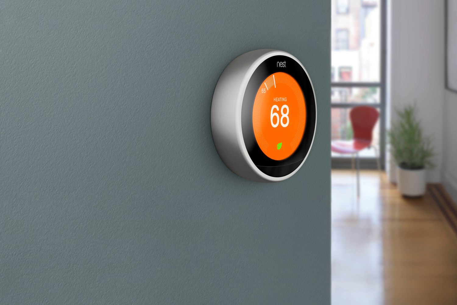
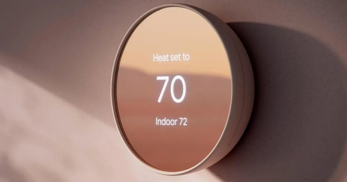
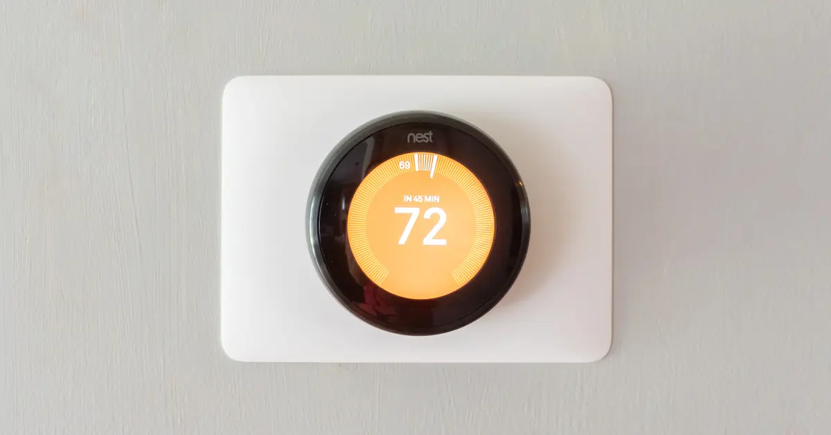
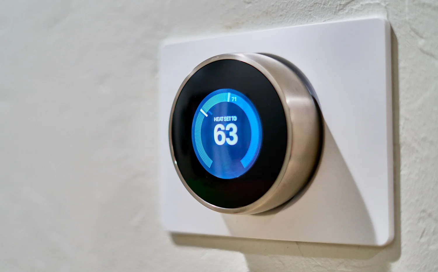
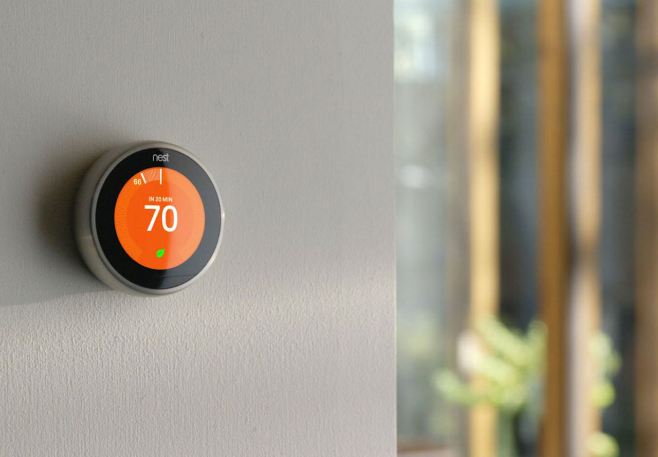
Welcome to the world of smart home technology! If you’ve ever wished you could control the temperature of your home with just a few taps on your smartphone, then you’re in the right place. In this guide, we will show you how to make your very own smart thermostat using some basic components and a little bit of programming.
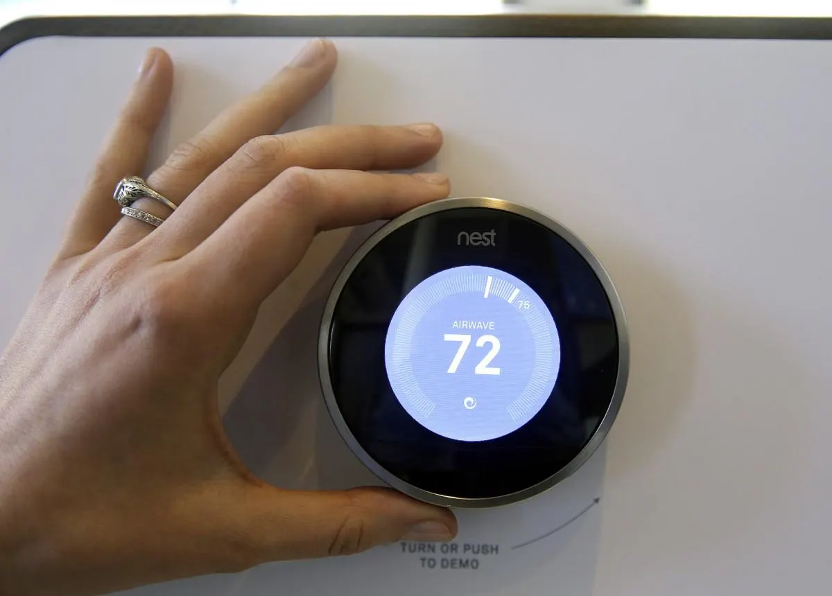
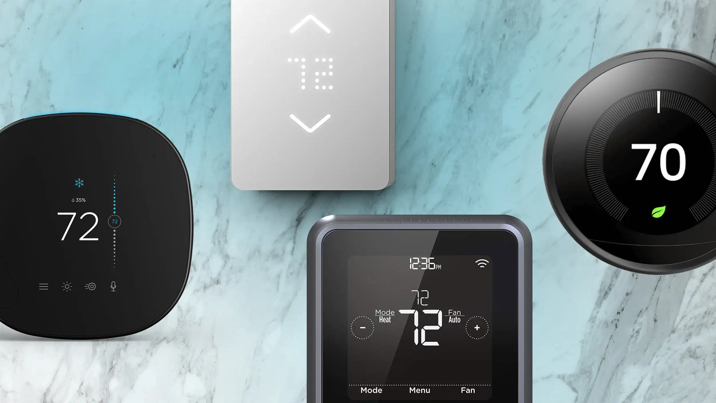
A smart thermostat allows you to remotely control the temperature of your home, providing convenience and energy efficiency. With the ability to set schedules and adjust settings from anywhere, you can ensure that your home is always comfortable while saving money on your energy bills.
This DIY project will require some basic knowledge of electronics and programming, but don’t worry if you’re new to these concepts. We will guide you through the process step by step, making it accessible for beginners.
To create your smart thermostat, you will need a few materials, including a microcontroller, a temperature sensor, a relay module, and some basic electronic components. You will also need a computer and some programming software.
In this tutorial, we will be using an Arduino microcontroller, which is beginner-friendly and widely available. However, feel free to use any other microcontroller that you’re comfortable with.
Ready to get started? Let’s gather the necessary components and embark on the journey of creating your very own smart thermostat.
Materials Needed
Before we dive into the steps of creating your smart thermostat, let’s gather all the materials you’ll need for this project. Here’s a list of the essentials:
- Arduino microcontroller (or a microcontroller of your choice)
- Temperature sensor (such as DHT11 or DS18B20)
- Relay module
- Breadboard
- Jumper wires
- USB cable
- Computer with Arduino IDE installed
- Wi-Fi module (optional, for remote control)
The Arduino microcontroller is the heart of your smart thermostat. It’s a programmable board that will control all the functions and interactions. You can find Arduino boards online or at your local electronics store.
The temperature sensor is used to measure the ambient temperature in your home. There are various options available, but popular choices include the DHT11 and DS18B20 sensors. These sensors can provide accurate temperature readings for your thermostat.
The relay module is responsible for controlling your heating or cooling system. It acts as a switch, allowing the microcontroller to turn the system on or off based on the temperature readings. Make sure to choose a relay that is compatible with your microcontroller and the voltage of your heating or cooling system.
A breadboard and jumper wires will be used to create the necessary connections between components. These provide a convenient way to prototype your circuit without the need for soldering.
To program the microcontroller, you’ll need a computer with the Arduino IDE (Integrated Development Environment) installed. The Arduino IDE is a software that allows you to write, compile, and upload code to your Arduino board.
Lastly, if you want to control your thermostat remotely, you can add a Wi-Fi module to your setup. This will enable you to connect your smart thermostat to your home network and control it through a smartphone app or a web interface.
Once you have gathered all the materials listed above, you’re ready to move on to the next steps of setting up your smart thermostat. Let’s get started!
Step 1: Gathering the necessary components
Before we begin assembling our smart thermostat, let’s gather all the necessary components. Having everything ready will streamline the setup process and ensure that we can proceed smoothly. Here is a list of the components you will need:
- Arduino microcontroller
- Temperature sensor (DHT11 or DS18B20)
- Relay module
- Breadboard
- Jumper wires
- USB cable
- Computer with Arduino IDE installed
- Wi-Fi module (optional)
Start by obtaining an Arduino microcontroller. The Arduino Uno is a popular choice due to its ease of use and wide availability. However, you can choose a different model if you prefer or already have one on hand.
Next, you’ll need a temperature sensor. Two commonly used options are the DHT11 and DS18B20 sensors. The DHT11 is a basic sensor that provides temperature and humidity readings, while the DS18B20 is a more precise digital temperature sensor.
The relay module is essential for controlling your heating or cooling system. Choose a relay that is compatible with your microcontroller and the voltage requirements of your system.
A breadboard will serve as the platform for assembling the circuit. It allows for easy connection and experimentation without any soldering. Use jumper wires to make the necessary connections between components on the breadboard.
Additionally, ensure you have a USB cable to connect the Arduino to your computer. The USB connection will be used to upload the code and power the microcontroller.
If you wish to control your thermostat remotely, you can include a Wi-Fi module. This module enables wireless connectivity and allows you to manage your thermostat through a smartphone app or web interface.
Make sure you have all the above components readily available before moving on to the next step. Having everything within reach will help streamline the process and make the setup more efficient.
With all the necessary components gathered, we are ready to proceed to the next step: setting up the microcontroller. Let’s get started!
Step 2: Setting up the microcontroller
Now that we have all the necessary components, let’s move on to setting up the microcontroller. Follow these steps to prepare your Arduino for the smart thermostat project:
- Connect your Arduino to your computer using the USB cable. This will provide power to the Arduino and allow you to program it.
- Open the Arduino IDE on your computer. If you haven’t installed it, you can download it from the Arduino website and follow the installation instructions.
- Select the appropriate Arduino board from the “Tools” menu in the IDE. For example, if you are using an Arduino Uno, choose “Arduino/Genuino Uno”.
- Choose the correct port for your Arduino. You can find this under the “Tools” menu as well. It will typically be named something like “COM3” or “/dev/tty.usbmodem1411” (the exact name may vary depending on your operating system).
- Test the connection by uploading a simple sketch to the Arduino. Open the “Blink” example sketch from the “File” menu and click the “Upload” button. If everything is set up correctly, the on-board LED on the Arduino should start blinking.
Once you have successfully set up the microcontroller and verified the connection, you are ready to proceed to the next step: connecting the temperature sensor. Let’s move on and continue building our smart thermostat!
Step 3: Connecting the temperature sensor
With the microcontroller set up, it’s time to connect the temperature sensor to our smart thermostat project. Follow these steps to properly connect the sensor:
- Take the temperature sensor (DHT11 or DS18B20) and identify the three pins on it. These are typically labeled VCC, GND, and DATA.
- Connect the VCC pin of the temperature sensor to the 5V pin on the Arduino.
- Connect the GND pin of the temperature sensor to any of the GND pins on the Arduino.
- For the DHT11 sensor, connect the DATA pin to a digital pin on the Arduino, such as pin 2. If you’re using the DS18B20 sensor, it uses the one-wire protocol and only requires a single digital pin.
- Double-check all the connections to ensure they are secure and properly inserted into the breadboard.
Connecting the temperature sensor allows the microcontroller to read temperature measurements and make decisions based on the data. The VCC and GND connections provide power to the sensor, while the DATA pin enables communication between the sensor and the microcontroller.
It’s essential to ensure the connections are correct and secure. A loose or incorrect connection can lead to malfunctioning or inaccurate readings from the sensor.
Once you have successfully connected the temperature sensor, you are ready to move on to the next step: wiring the relay module. Let’s proceed to the next step and continue building our smart thermostat!
Step 4: Wiring the relay module
With the temperature sensor successfully connected, the next step is to wire the relay module for controlling the heating or cooling system. Follow these steps to properly wire the relay module:
- Identify the control pins on the relay module. These are typically labeled IN1, IN2, IN3, etc.
- Connect one of the control pins to a digital pin on the Arduino. For this example, we will use digital pin 3. You can choose any available digital pin, but remember to update the pin number in your code later.
- Connect the VCC pin of the relay module to the 5V pin on the Arduino.
- Connect the GND pin of the relay module to any of the GND pins on the Arduino.
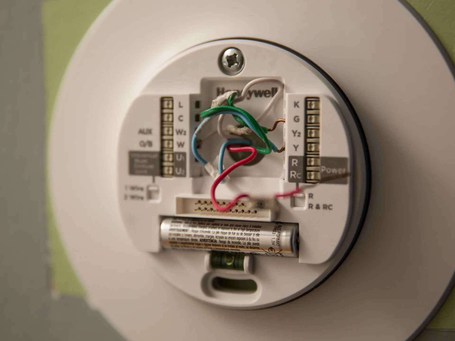
- Identify the input pins on the relay module. These are typically labeled NC (Normally Closed), NO (Normally Open), and COM (Common).
- Connect the COM pin to the power supply (e.g., 120V AC or 220V AC) of your heating or cooling system.
- Connect the NO pin to the wire that goes to the heating or cooling device.
- Double-check all the connections to ensure they are secure and properly inserted into the breadboard.
Wiring the relay module allows the microcontroller to switch the heating or cooling system on or off based on the temperature readings. The control pins on the relay module connect to the Arduino, while the input pins are connected to the power supply and the device being controlled.
Take extra care when working with high voltage connections. Ensure that all power is switched off before making any connections, and be cautious to avoid any short circuits or exposed wiring.
Once you have wired the relay module, move on to the next step: creating the user interface for your smart thermostat. Let’s continue building our smart thermostat!
Step 5: Creating the user interface
Now that we have the hardware aspects set up, it’s time to create a user interface for our smart thermostat. The user interface will allow us to interact with the thermostat and set our desired temperature. Follow these steps to create the user interface:
- Open the Arduino IDE on your computer.
- Click on “File” and then “Examples”. Scroll down to find the “LiquidCrystal” library and select one of the example sketches.
- Connect the LCD screen to the Arduino using jumper wires. Make sure to connect the VCC and GND pins of the LCD screen to the 5V and GND pins of the Arduino, respectively. Connect the SDA and SCL pins of the LCD screen to the corresponding pins on the Arduino (usually A4 and A5).
- Upload the example sketch to the Arduino and test if the LCD screen is displaying the desired output.
- Modify the example sketch to suit the requirements of your smart thermostat. This may include adding buttons for adjusting temperature, displaying current temperature readings, and any other features you desire.
- Test the modified sketch on the Arduino to ensure that the user interface is functioning correctly.
The user interface is an essential component of our smart thermostat, as it allows us to interact with the system and easily set our desired temperature. The LCD screen serves as the display, while buttons or other input devices can be used to adjust the temperature or navigate through the interface.
By utilizing the LiquidCrystal library in the Arduino IDE, we can create custom displays and control the content shown on the LCD screen. The example sketches provided with the library can serve as a starting point, and you can modify them to meet the specific requirements of your smart thermostat design.
Once you have created and tested the user interface, we can move on to the next step: programming the thermostat to control the temperature based on the user inputs and sensor readings. Let’s proceed and continue building our smart thermostat!
Step 6: Programming the thermostat
With the user interface set up, it’s time to program the thermostat to control the temperature based on user inputs and sensor readings. The programming will allow the microcontroller to make decisions and carry out the desired actions. Follow these steps to program the thermostat:
- Open the Arduino IDE on your computer.
- Create a new sketch and give it an appropriate name.
- Start by including any necessary libraries for the temperature sensor, LCD display, and other components you are using.
- Define any constants and variables needed for your program. This may include pin assignments, temperature thresholds, and user input variables.
- Set up the necessary functions to initialize the components, read temperature values, display information on the LCD, and control the relay module.
- Write the main loop that continuously reads the temperature, compares it to the desired temperature set by the user, and turns the heating or cooling system on or off accordingly.
- Upload the code to the Arduino and monitor the serial output for any debugging or troubleshooting.
- Test the functionality of the thermostat by adjusting the desired temperature and observing how the system responds.
- Make any necessary adjustments or refinements to the code to optimize its performance and behavior.
Programming the thermostat is a crucial step in making it an intelligent and responsive device. By writing code that utilizes the sensor readings and user inputs, we can create a thermostat that adjusts the temperature automatically and maintains a comfortable environment.
Keep in mind that the exact programming details will depend on the components you are using and the desired functionality of your thermostat. It’s important to thoroughly test the code and make any necessary modifications to ensure its accuracy and reliability.
Once you have successfully programmed the thermostat, you are now ready for the final step: testing and troubleshooting. Let’s proceed and ensure our smart thermostat is working as intended!
Step 7: Testing and troubleshooting
After completing the programming of your smart thermostat, it’s crucial to thoroughly test and troubleshoot to ensure that it functions correctly and reliably. Follow these steps to test and troubleshoot your smart thermostat:
- Power on the thermostat and monitor the readings displayed on the LCD screen. Verify that the temperature readings are accurate and consistent with the actual temperature in the room.
- Set a desired temperature using the user interface and observe how the thermostat responds. It should activate the heating or cooling system when the temperature drops below the set threshold and turn it off when the temperature reaches the desired level.
- Make adjustments to the temperature thresholds or other parameters in the code if necessary. Ensure that the system is responsive and maintains the desired temperature accurately.
- Test different scenarios, such as increasing or decreasing the set temperature rapidly, to see if the thermostat adjusts accordingly and operates as expected.
- Monitor the performance of the system over an extended period to ensure its stability and consistency. Keep an eye out for any irregularities or unexpected behavior.
- If you encounter any issues, use the Arduino IDE’s serial monitor to debug and identify the problem. Check for any error messages or unexpected readings that may indicate a problem in the code or hardware connections.
- Double-check all the hardware connections and components to ensure that they are securely connected and functioning properly.
- Refer to the documentation and online resources for troubleshooting tips specific to the components and libraries you are using.
- Make any necessary adjustments or modifications to the code or hardware to resolve any issues or improve the performance of the smart thermostat.
Testing and troubleshooting are essential to ensure the functionality and reliability of your smart thermostat. Keep in mind that every system is unique, and issues may arise during the testing phase. Patience and persistence are key as you work through any challenges that may arise.
Once you have successfully tested and troubleshooted your smart thermostat, congratulations! You have now completed the process of creating your very own smart thermostat from scratch. Enjoy the convenience and energy efficiency it brings to your home!
Conclusion
Congratulations on successfully creating your very own smart thermostat! Through the process of gathering the necessary components, setting up the microcontroller, connecting the temperature sensor, wiring the relay module, creating the user interface, programming the thermostat, and finally testing and troubleshooting, you have built a device that allows you to control the temperature of your home with convenience and efficiency.
A smart thermostat offers numerous benefits, such as remote control capabilities, energy savings, and personalized comfort. By following the step-by-step instructions in this guide, you have acquired the skills to create and customize a smart thermostat tailored to your specific needs.
Remember to always prioritize safety when working with electronics and high voltage connections. Double-check all the connections and ensure that you are following proper safety guidelines throughout the project.
Feel free to explore further possibilities with your smart thermostat. You may consider adding additional features, such as humidity control, voice activation, or integration with smart home automation systems.
We hope this guide has empowered you to take control of your home’s temperature through the creation of a smart thermostat. Enjoy the convenience, energy efficiency, and comfort that your smart thermostat brings to your everyday life!


