




To build a drone with Arduino, you need to assemble a quadcopter frame, wire brushless motors and electronic speed controllers (ESCs), connect an MPU6050 gyroscope and accelerometer, and program an Arduino board with the MultiWii open-source flight controller firmware. If you ever need to safely disable unauthorized drones in your airspace, you can build a drone jammer as a countermeasure. For a deeper understanding of frame design and component selection before you start wiring, you can build a drone from scratch without relying on a pre-made flight controller. This guide walks through the physical assembly, wiring, and programming steps to create a fully functional quadcopter that you can fly with a standard radio transmitter.
How to build a drone with Arduino: what you'll need
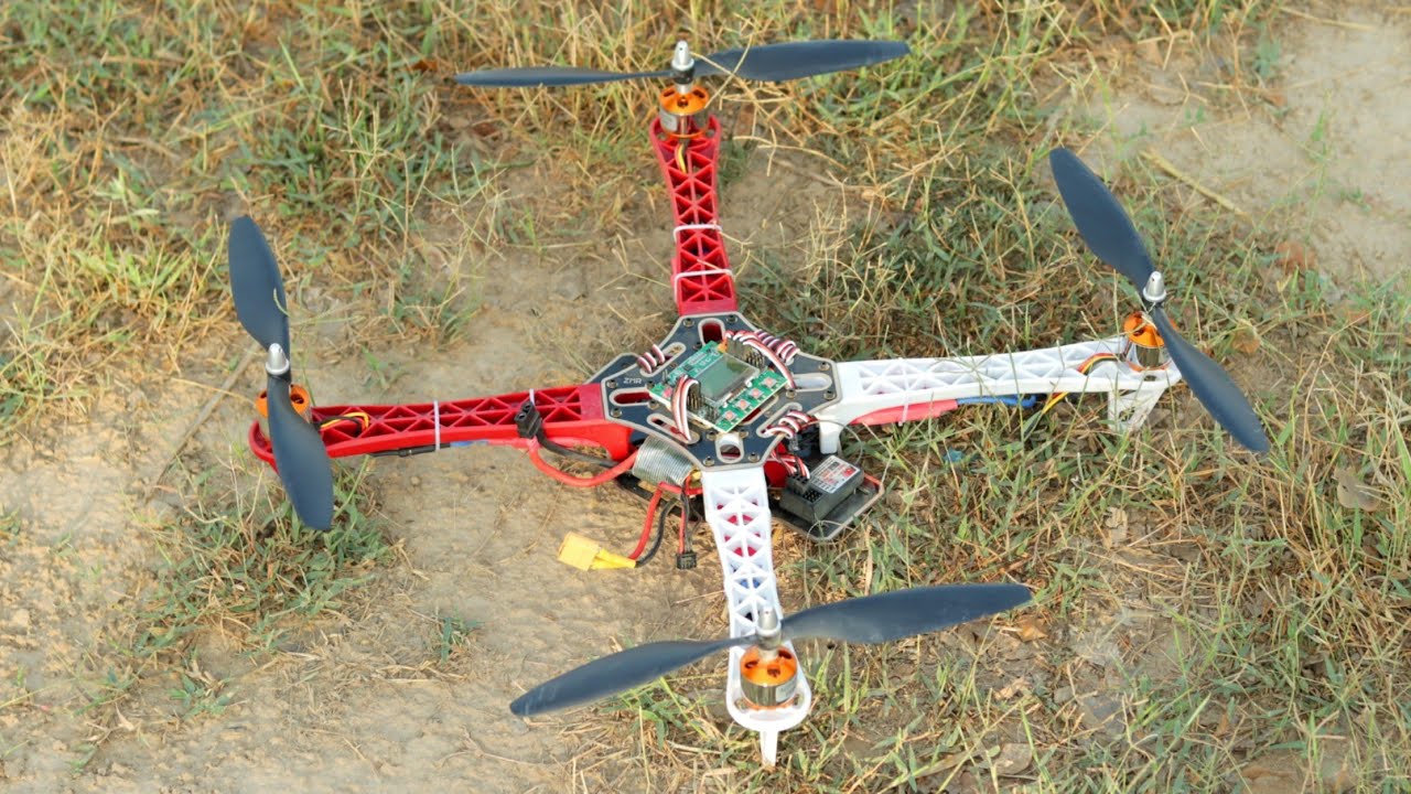
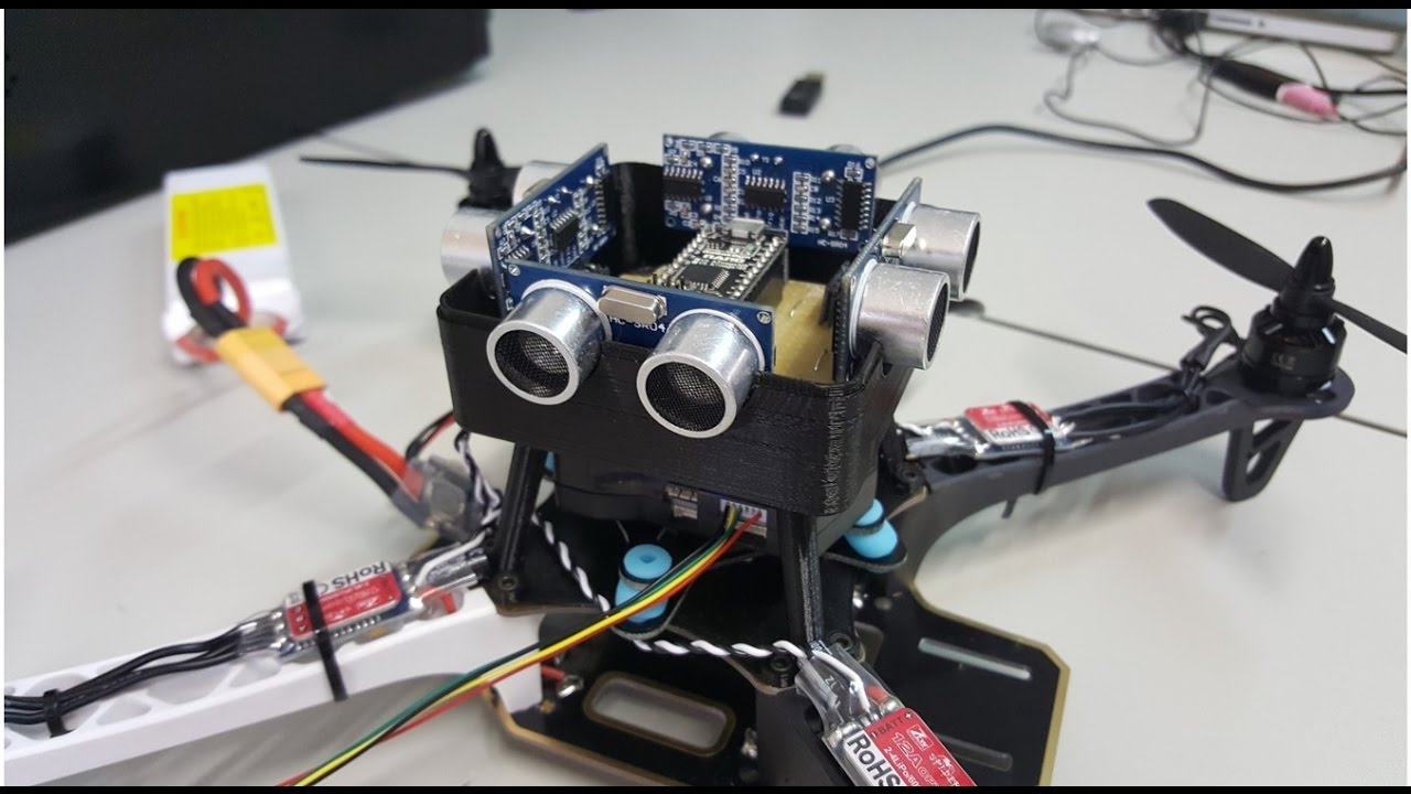
Building a drone with Arduino is a practical project that results in a flying quadcopter controlled by the MultiWii firmware. You will need a frame kit with arms and plates, four brushless motors, four electronic speed controllers (ESCs), an Arduino board (such as the Uno or Nano), an MPU6050 inertial measurement unit (IMU), a radio transmitter and receiver, a power distribution board or pad, a lithium polymer (LiPo) battery, and propellers. The goal is to build a MultiWii-based quadcopter that is stable, responsive, and ready for flight.
Step 1: Assembling the frame and mounting the motors
Begin by attaching the arms to the main body plates of the frame kit. Align each arm symmetrically and secure them with the provided screws or fasteners. Once the arms are fixed, mount the brushless motors to the ends of the arms using the included mounting hardware. Tighten all screws firmly, ensuring the motors are seated flat and cannot shift during flight. Double-check that the frame is rigid and all components are aligned before proceeding.
Step 2: Wiring the ESCs, motors, and power distribution
- Connect the three wires from each brushless motor to its corresponding ESC. Match the wire colors or label the connections; if a motor spins the wrong direction later, you will swap any two of these three wires.
- Solder or securely connect the power input wires (red and black) from each ESC to a power distribution board or a central power pad. Ensure the polarity is correct, red to positive, black to negative.
- Connect the signal wire and ground wire from each ESC to the designated motor output pins on the Arduino board. Refer to the MultiWii pin mapping for your Arduino model to identify the correct pins for motor 1, motor 2, motor 3, and motor 4.
- Organize all wiring with zip ties or tape, routing it away from moving parts and propellers.
Step 3: Connecting the MPU6050 IMU and radio receiver
- Wire the MPU6050 gyroscope and accelerometer module to the Arduino’s I2C pins. Connect the module’s SDA pin to the Arduino’s analog pin A4 (or the dedicated SDA pin on other boards) and the SCL pin to analog pin A5 (or the dedicated SCL pin). Also connect VCC to 5V and GND to ground.
- Connect your radio receiver to the Arduino according to the MultiWii schematic. The receiver’s channel outputs (typically throttle, roll, pitch, yaw, and auxiliary channels) go to specific digital input pins on the Arduino. Verify the pin assignments in the MultiWii documentation for your board type.
- Ensure all connections are secure and double-check that no wires are crossed or shorted.
Step 4: Programming the Arduino with the MultiWii firmware
- Download the MultiWii firmware from the official repository and extract the files.
- Open the MultiWii sketch in the Arduino IDE.
- Edit the
Config.hfile to define your quadcopter configuration. Uncomment the line for a quadcopter frame (e.g.,#define QUADXfor an X configuration) and select the correct sensor board (e.g.,#define MPU6050). Adjust any other settings as needed for your specific hardware. - Remove the Arduino from the flight controller board, then connect it to your computer via a USB cable.
- In the Arduino IDE, go to the Tools menu, select Board, and choose the correct Arduino model. Then select the appropriate COM port under Tools > Port.
- Click the Upload button (right arrow icon) to compile and upload the firmware to the Arduino.
- After upload, disconnect the USB cable and reinstall the Arduino onto the frame.
Step 5: Testing, troubleshooting, and first flight
- Perform a pre-flight check: verify that all screws are tight, wiring is secure, and the battery is fully charged.
- Connect the flight controller to the MultiWii GUI (MultiWiiConf or similar) via USB. Use the motor test function to verify each motor spins in the correct direction. If a motor spins backward, swap any two of its three wires at the ESC connection.
- In the GUI, check that the radio receiver channels respond correctly to your transmitter’s stick movements. Calibrate the accelerometer and radio endpoints if needed.
- Secure all wiring with zip ties and ensure nothing will catch on the propellers.
- Take the drone to a safe, open area away from people and obstacles. Arm the motors and perform a low-altitude hover test. If the drone drifts or wobbles, land immediately and adjust the PID settings in the GUI or recalibrate the sensors.
- Repeat test flights, making small adjustments, until the drone hovers stably and responds predictably to your controls.
Going further: adding GPS and a barometer
For advanced drone functionalities such as altitude hold and position lock, additional sensors like a barometer and a GPS module can be integrated. Wire the barometer to the Arduino’s I2C bus (often sharing the same SDA/SCL lines as the MPU6050) and connect the GPS module to a serial port. Then edit the Config.h file to enable the corresponding features (e.g., #define BARO and #define GPS). Re-upload the firmware and configure the new features in the MultiWii GUI. With these additions, your drone can hold a fixed altitude and return to a set home position, expanding its capabilities far beyond basic flight. The book Drones: Buying, Building and Flying covers the full spectrum of the hobby, from buying, building and flying drones to advanced modifications.