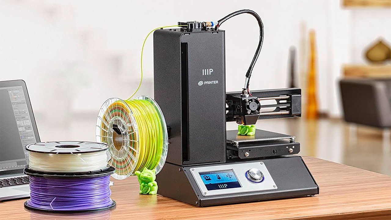





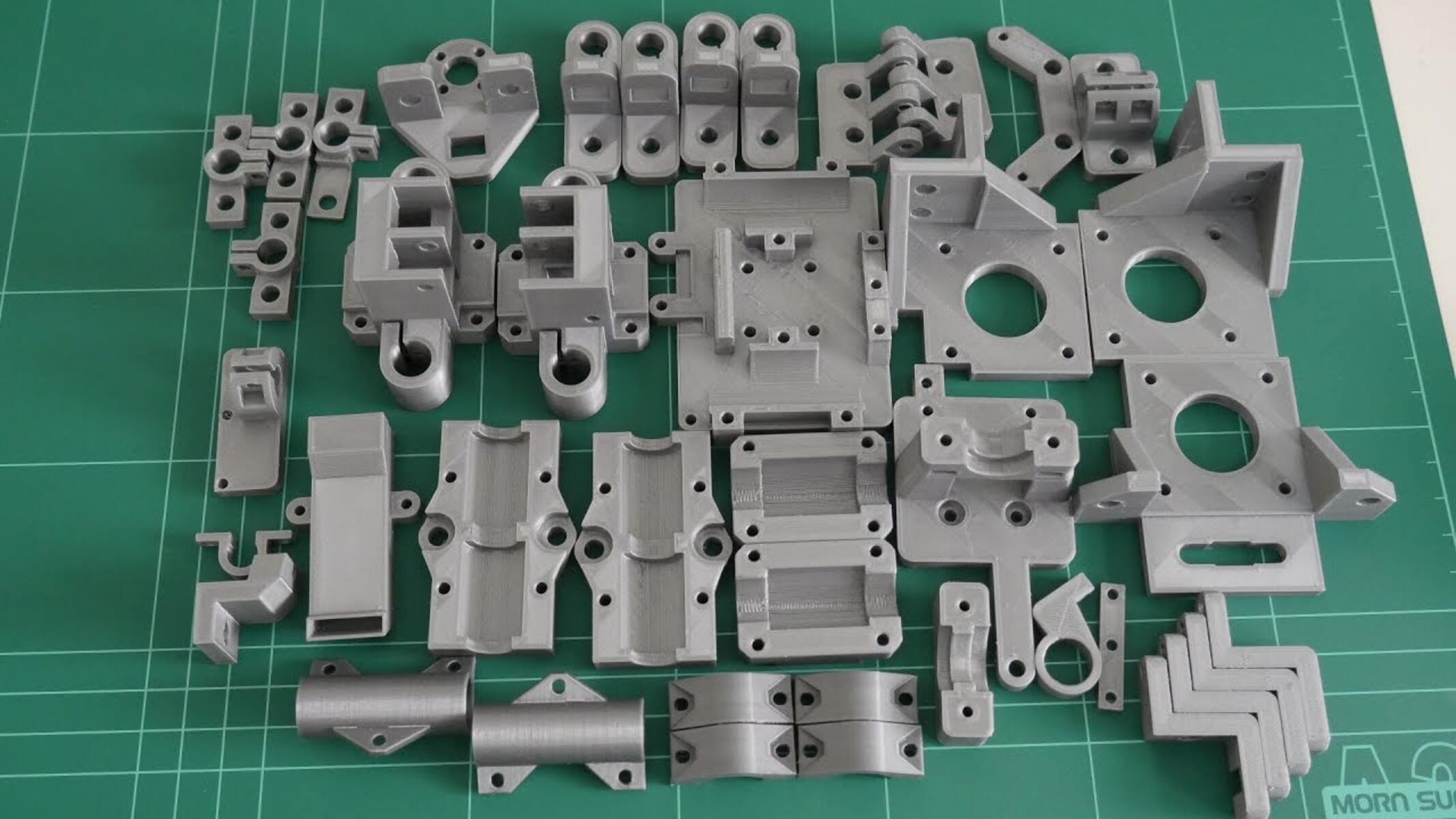
To replicate a plastic part with a 3D printer, you must first digitize the original object using one of three methods, 3D scanning, manual CAD modeling with calipers, or photogrammetry, then prepare that digital model and print it in a suitable hard plastic filament like PETG or ABS. The fastest path for a broken or discontinued part is 3D scanning, while manual CAD offers the most control when you only have a rough reference or need to add design improvements. If you are new to the process, you can use an iiip 3D printer to handle these durable filaments reliably right out of the box. If a spool runs out mid-print, knowing how to change filament during 3D printing keeps the job from failing.
How to replicate a plastic part with a 3D printer: Immediate step-by-step overview of the three replication methods and
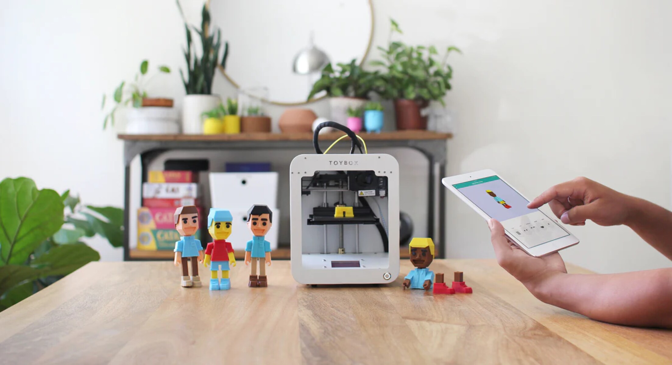
You have three primary routes to turn a physical plastic piece into a printable 3D model. 3D scanning uses a handheld or desktop scanner to capture the geometry automatically, best for complex organic shapes or parts with intricate curves. Manual CAD involves measuring every dimension with calipers and rebuilding the part from scratch in software like Fusion 360 or Blender, ideal for simple, prismatic parts or when you need to modify the design. Photogrammetry takes dozens of overlapping photos from different angles and stitches them into a 3D mesh using software like Meshroom, a budget-friendly option that works well for medium-sized parts with good surface texture. Once your model is ready, you can use toybox 3D printer to bring it to life with kid-friendly, one-touch operation.
For the filament choice, PETG is the default for functional replicas because it combines ease of printing (no enclosed chamber needed) with excellent layer adhesion, impact resistance, and chemical durability. ABS is stronger under heat and more rigid, but it requires an enclosed printer to prevent warping and emits fumes.
Tools and materials you need to replicate a part
Before starting, assemble the following essentials:
- 3D scanner (e.g., EinScan, Revopoint) OR digital calipers (for manual CAD) OR a camera (for photogrammetry)
- CAD software (Fusion 360, Blender, or FreeCAD) for model creation/repair
- Mesh repair tool (Meshmixer or Netfabb) to fix scan errors
- Slicer software (Cura, PrusaSlicer) to generate G-code
- 3D printer with a build volume larger than your part
- PETG or ABS filament in the appropriate color
- Support removal tools (pliers, flush cutters)
- Sandpaper (120-400 grit) and calipers for final verification
Capturing the shape: from physical part to digital 3D model
Method 1: 3D scanning the original part
- Clean the part thoroughly to remove dirt, grease, or reflective tape, these cause scan artifacts.
- Calibrate the scanner according to the manufacturer’s instructions, then place the part on a matte, non-reflective surface.
- Scan the part from multiple angles, rotating it slowly.
- Review the scan in the scanner’s software; fill any holes using the “close holes” or “mesh repair” function.
- Export the mesh as an STL or OBJ file.
Method 2: Manual CAD with calipers
- Measure the part’s overall dimensions (length, width, height) with calipers and note them.
- Measure critical features: hole diameters, boss heights, wall thicknesses, and any chamfers or fillets.
- In your CAD software, create a new sketch and draw the base profile using the measured dimensions.
- Extrude the profile to the measured height, then add or subtract features (holes, slots, ribs) using the exact coordinates.
- Use the “measure” tool in CAD to verify every dimension matches your caliper readings before exporting as STL.
Method 3: Photogrammetry (budget option)
- Place the part on a turntable with a textured background (e.g., a patterned mat).
- Clean the resulting mesh by removing floating artifacts and filling holes in Meshmixer.
- Export as STL.
Preparing and optimizing the 3D model for printing
Regardless of capture method, your STL will likely contain errors, non-manifold edges, inverted normals, or holes. Open the file in Meshmixer or Netfabb and run the “auto-repair” function. Then check the model’s scale against the original part’s measurements; adjust the scale factor in your slicer if needed.
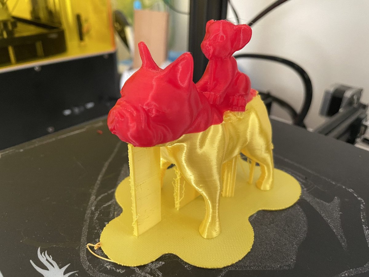
Tree supports work best for organic shapes, while line supports are more rigid for flat overhangs.
Adjusting print settings for a functional duplicate
For a mechanical part that must withstand load, set infill density to 40% using a grid or gyroid pattern; this provides strength without excessive material use.
Printing and monitoring your plastic replica
- Slice the model and transfer the G-code to your printer via SD card, USB, or Wi-Fi.
- Preheat the nozzle and bed, then start the print.
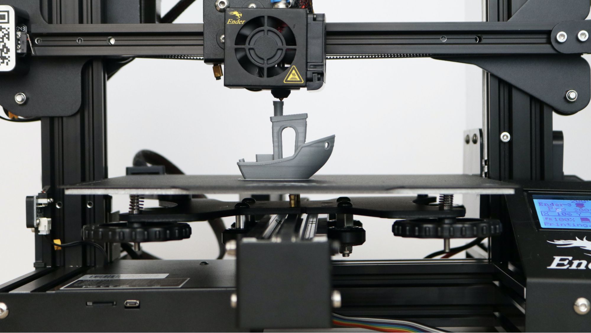
- Watch the critical first layer adhesion, the filament should squish slightly onto the bed, forming a smooth, continuous line. If it beads up, increase bed temperature or lower the Z-offset.
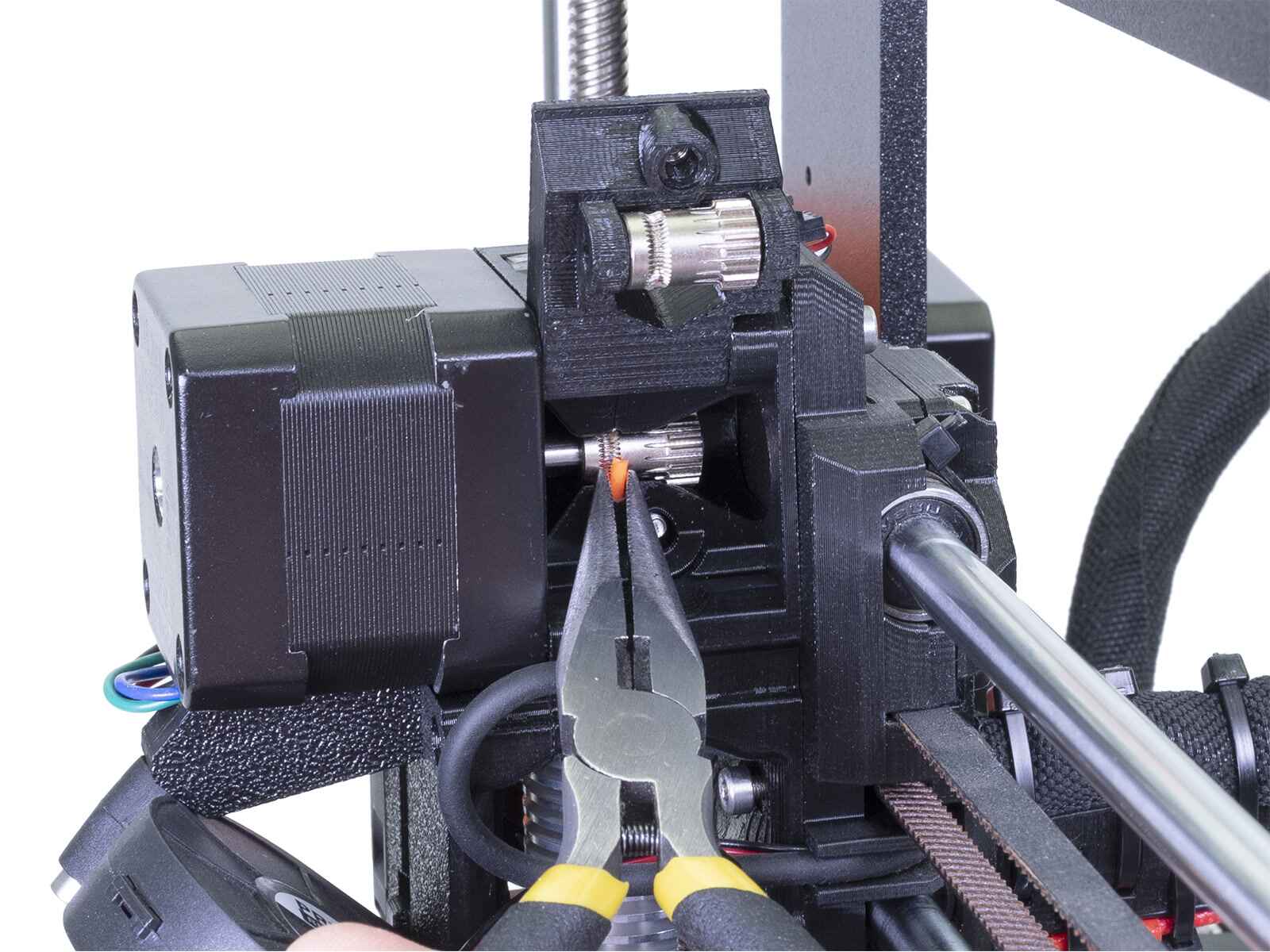
- For mid-print issues like filament jams or clogs, pause the print and follow our filament change guide.
Finishing touches and post-processing for accuracy
- Remove support structures carefully using pliers or a deburring tool, work from the base upward to avoid breaking the part.
- Clean the part with isopropyl alcohol to remove dust and grease.
- Check dimensional accuracy with calipers: measure critical diameters, hole sizes, and overall length. Compare against the original part; if the replica is 0.2-0.5 mm larger, it’s due to filament shrinkage, adjust the scale factor by 0.5-1% in your slicer and reprint.
- Test-fit the replica in its intended application. If it’s too tight, sand the mating surfaces; if too loose, apply a thin layer of epoxy or use a heat-set insert for a press fit.
- For a professional finish, apply acetone vapor smoothing (ABS only) or a clear acrylic spray to seal the surface.