




How to set up a network switch and patch panel: Overview of the physical installation sequence
To set up a network switch and patch panel, you mount both components in a rack, terminate the horizontal cables onto the patch panel using the T568B standard, then use short patch cords to connect the panel ports to the switch. The sequence runs from rack mounting, through cable routing and termination, to final testing and labeling.
Tools and equipment you need
Before starting, gather a punch-down tool with a 110-blade for terminating wires onto the patch panel, a cable tester for verifying continuity, Velcro ties for cable management, rack screws for securing equipment, and the switch and patch panel themselves. A wire stripper and a cable cutter are also essential for preparing the Ethernet cables. You do not need a crimping tool because the patch panel’s punch-down block replaces RJ45 connectors on the horizontal runs.
Mounting the patch panel and switch in the rack
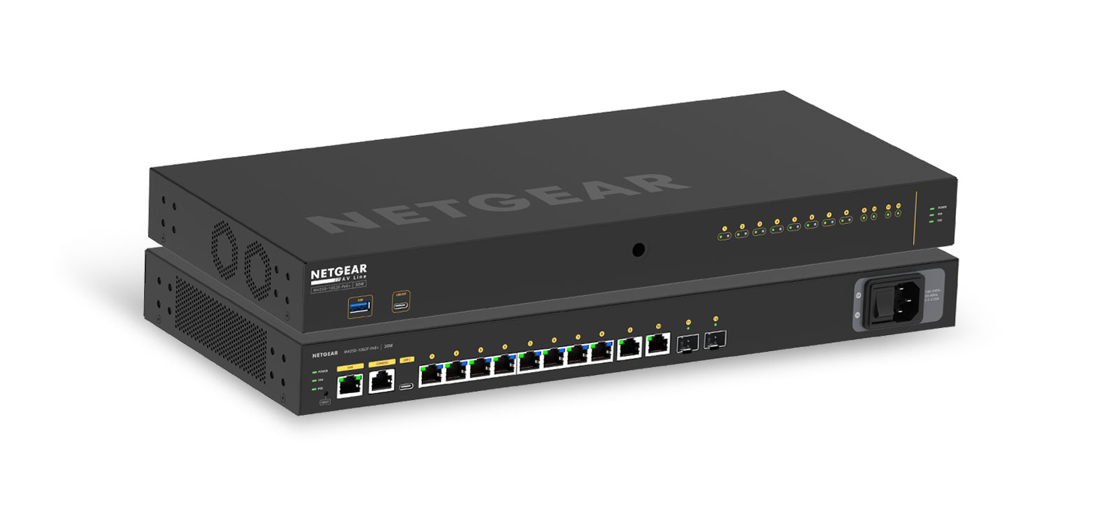
Position the patch panel in a 19-inch equipment rack or on a wall mount, and secure it with rack screws at both ends. Mount the network switch directly below or above the patch panel, leaving one rack unit of space between them for airflow and cable access. Ensure the switch’s ventilation ports are not blocked by cables or other equipment, and confirm that the rack has enough depth to accommodate the switch’s rear ports and power connector. Once physically installed, you can configure a managed network switch to set up VLANs and prioritize traffic. For wall-mounted installations, use a bracket rated for the combined weight of both devices.
Routing and dressing the Ethernet cables
Run the horizontal Ethernet cables from their wall jacks or endpoints to the rear of the patch panel. Do not use zip ties on the horizontal runs, as over-cinching can deform the cable jacket and alter the twist ratio of the internal pairs.
Terminating cables on the patch panel (T568B standard)
Strip back approximately 1 inch of the cable jacket, then untwist the four wire pairs. Following the T568B color sequence, orange-white, orange, green-white, blue, blue-white, green, brown-white, brown, seat each wire into its corresponding punch-down slot on the rear of the patch panel. Use the punch-down tool to push each wire into the slot, trimming the excess conductor as you go. Keep the untwist length at the contact point to a strict maximum of 0.5 inches (13 mm); any longer and crosstalk between pairs will degrade signal quality. Repeat for every cable, working from left to right across the panel to avoid tangling the already-terminated wires.
Connecting patch cables from the panel to the switch
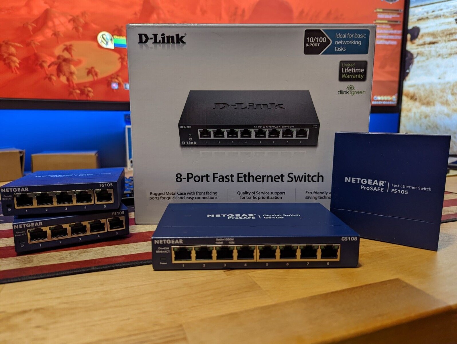
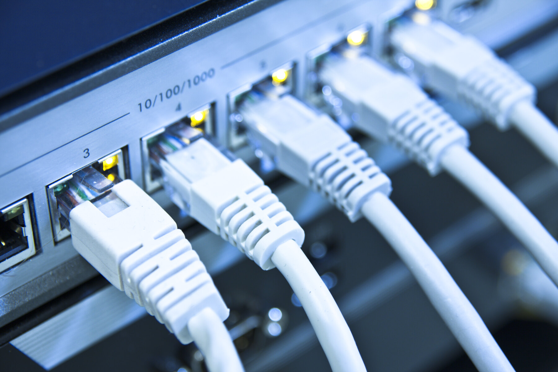
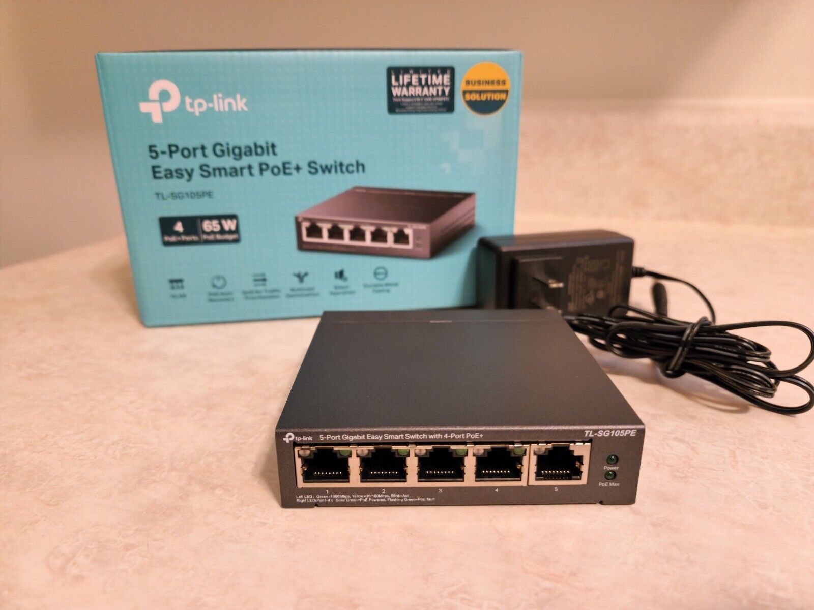
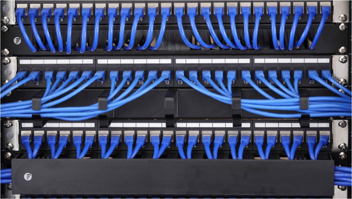
Once all horizontal cables are terminated, use short patch cords, typically 0.5 to 3 feet in length, to link each patch panel port to a corresponding port on the network switch. If you need a reliable switch for this setup, you can set up TP-Link 5-port gigabit Ethernet network switch in minutes. Plug the patch cord into the front of the patch panel port, then into the switch port directly below it. Keep the patch cords flat and untangled, routing them through the horizontal cable managers between the panel and switch.
Powering and connecting the unmanaged switch to the network
Power off all devices that will connect to the switch before making any electrical connections. Position the switch in a central, well-ventilated location within the rack, then connect its power adapter to a surge-protected outlet. Take an Ethernet cable from the router’s LAN port and plug it into one of the switch’s uplink ports, on most unmanaged switches, any port can serve as the uplink. Then connect end devices such as computers, printers, or access points to the remaining switch ports using their own Ethernet cables. Power on the switch first, wait for it to initialize, then power on the connected devices one at a time.
Labeling all cables and ports clearly
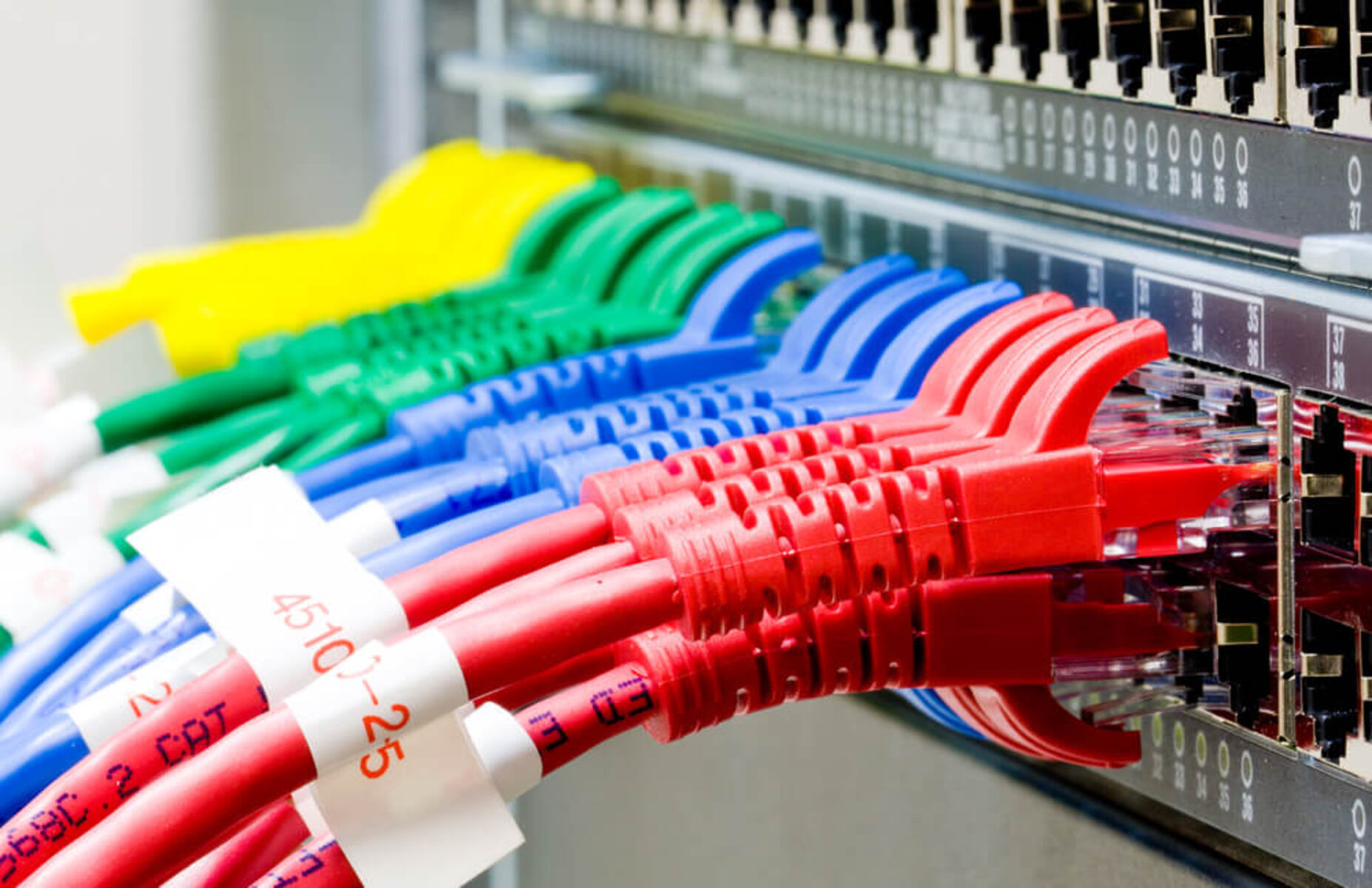
Write the same identifier on the corresponding patch panel port, either on the front label strip or directly above the port. For the patch cords, label each end with the destination device name or port number. This step is critical for immediate identification during troubleshooting: when a user reports a dead connection, you can trace the patch cord to the panel port, then to the horizontal cable label, and know exactly which wall jack or device is affected.
Testing and certifying your connections
Use a wiremap tester to verify that each terminated cable has the correct pin-to-pin continuity. Connect the tester’s main unit to one end of the horizontal cable and the remote unit to the wall jack, then check that the display shows all eight wires in the correct T568B order. A wiremap test confirms basic wiring correctness, but it does not measure signal quality. If you are installing cable that must support gigabit speeds or Power over Ethernet, you need a full network certifier to measure crosstalk, return loss, and insertion loss against category standards. For most home and small office setups, a wiremap test is sufficient; for commercial installations where the cabling must pass a warranty inspection, hire a technician with a certifier. After testing, power on all devices and verify that each one obtains an IP address and can reach the internet or local resources. For an unmanaged switch, no configuration is required beyond the physical connections.
For the wider topic, see use a network switch with 2 routers.