Introduction
Welcome to the world of 3D scanning! In recent years, 3D scanning technology has become increasingly popular for various applications, ranging from industrial design and medical imaging to virtual reality and 3D printing. A 3D scanner allows you to capture the shape and geometry of physical objects and create digital replicas that can be manipulated and transformed in a virtual space.
In this article, we will explore how you can use a 3D scanner with Arduino, a popular open-source electronics platform. Arduino provides a flexible and customizable platform for building your own 3D scanner, allowing you to dive into the exciting world of 3D scanning without breaking the bank.
By combining the power of Arduino with a 3D scanner, you can unleash your creativity and transform real-world objects into digital models that can be manipulated, analyzed, or even reproduced through 3D printing. Whether you’re a hobbyist, student, or professional, learning how to use a 3D scanner with Arduino opens up a wide array of possibilities for your projects and designs.
Throughout this article, we will guide you step-by-step through the process of setting up and using a 3D scanner with Arduino. We will cover the essential components needed, the wiring process, calibration, programming the Arduino, capturing 3D scans, and post-processing the scanned data.
So, if you’re ready to embark on a journey into the fascinating world of 3D scanning, grab your Arduino board and let’s get started!
What is a 3D Scanner?
A 3D scanner is a device used to capture the three-dimensional shape and geometry of real-world objects. It works by emitting various types of energy, such as laser beams or structured light patterns, onto an object and measuring the reflections or distortions produced.
The main goal of a 3D scanner is to create a digital representation of a physical object, known as a 3D scan or point cloud. This scan can then be used for a wide range of applications, including reverse engineering, quality control, virtual reality, animation, and 3D printing.
There are different types of 3D scanners available, each using different technologies and principles to capture 3D data. Some common types include laser scanners, structured light scanners, time-of-flight scanners, and photogrammetry-based scanners.
Laser scanners emit laser beams and measure the time it takes for the beam to bounce back from the object’s surface. This data is used to calculate the distance and shape of the object’s surface points. Structured light scanners project patterns onto the object’s surface and use cameras to capture the patterns’ distortions, which are then used to reconstruct the surface geometry.
Time-of-flight scanners measure the time it takes for light or other electromagnetic waves to travel to the object and back, allowing them to calculate the distance and shape of the scanned surface. Photogrammetry-based scanners capture multiple images of an object from different angles and use complex algorithms to calculate the object’s shape and surface details.
Overall, regardless of the specific technology used, 3D scanners play a vital role in capturing detailed and accurate representations of physical objects in digital form. With the advancements in technology, 3D scanning has become more accessible and affordable, opening up new possibilities for various industries and creative endeavors.
How Does a 3D Scanner Work?
A 3D scanner works by capturing the geometry and shape of an object through a process called digitization. This process involves scanning the object from various angles and collecting data points that represent the object’s surface or structure. These data points are then combined and processed to create a digital 3D model of the object.
The exact mechanism of a 3D scanner can vary depending on the type of technology used, but the fundamental principle remains the same. Let’s take a look at the general steps involved in the 3D scanning process:
- Preparation: Before scanning, the object needs to be prepared to ensure optimal results. This may involve cleaning the object, applying a coating to enhance visibility, or positioning it in a controlled environment.
- Data Capture: The 3D scanner emits energy, such as laser beams or structured light patterns, onto the object’s surface. Sensors or cameras in the scanner capture the reflections, distortions, or time it takes for the energy to travel back to the scanner. These measurements provide essential data about the shape and geometry of the object.
- Data Processing: Once the data is captured, it undergoes a series of processing steps to convert it into a usable 3D model. This may involve aligning and merging multiple scans, removing noise or artifacts, and creating a dense point cloud that represents the object’s surface in 3D space.
- Mesh Generation: The point cloud is further processed to create a mesh, which defines the object’s surface as a collection of interconnected polygons. This mesh can then be used for visualization or further refinement.
- Texture Mapping: In some cases, the scanner may also capture texture information, such as color or texture patterns of the object’s surface. This information can be mapped onto the mesh to add realistic texture to the 3D model.
- Post-Processing: After generating the 3D model, post-processing steps may be performed to clean up the model, fill in any gaps or missing data, and optimize it for specific applications.
Each step in the 3D scanning process plays a crucial role in creating an accurate and detailed representation of the object. The technology and techniques used in 3D scanners continue to evolve, enabling faster, more precise scanning and expanding the range of objects that can be digitized.
Components Needed for Using a 3D Scanner with Arduino
To build and use a 3D scanner with Arduino, you will need a few essential components. These components will allow you to capture and process the necessary data for creating a digital representation of the scanned object. Let’s take a look at the key components you’ll need:
- Arduino Board: The Arduino board serves as the central control unit for your 3D scanner. It provides the necessary computing power and I/O capabilities to interface with other components and execute the scanning process. There are various Arduino board models available, such as Arduino Uno, Arduino Mega, or Arduino Leonardo, which offer different features and capabilities.
- 3D Scanner Hardware: The hardware components of a 3D scanner include a laser module or structured light projector, a camera or cameras, and a mechanical mechanism for moving the scanner or the scanned object. The laser module or structured light projector emits the energy used for scanning, while the camera captures the reflections or distortions. The mechanical mechanism ensures controlled movement to capture data from different angles.
- Stepper Motors: Stepper motors are essential for precise and controlled movement in the scanning process. They allow you to move the scanner or the object with the required accuracy and speed. Stepper motors can be connected to the Arduino board using appropriate motor drivers or motor control modules.
- Motor Drivers: Motor drivers are electronic devices that provide the necessary power and control signals to drive stepper motors. They interface between the Arduino board and the stepper motors, ensuring smooth and accurate movement during the scanning process. Different motor drivers support specific motor types and have varying current and voltage ratings.
- Power Supply: A stable and reliable power supply is crucial for proper functioning of the 3D scanner components. The Arduino board, motors, laser module, and other devices will require appropriate power sources. Ensure that the power supply can deliver the required voltage and current to all components consistently.
- Connecting Cables: You will need various cables, such as jumper wires, USB cables, and motor cables, to connect the different components together. Make sure to select cables that are compatible with the connectors and interfaces of the Arduino board and other devices.
- Mounting Structure: Depending on the design and size of your 3D scanner, you may need a suitable mounting structure or frame to securely hold all the components in place. This structure should provide stability and allow for adjustable positioning of the scanner and object during the scanning process.
These are the essential components you will need to build and use a 3D scanner with Arduino. While the specific components may vary based on your project requirements, having these key elements will provide a solid foundation for constructing a functional 3D scanner.
Setting up Arduino for 3D Scanning
Before you can start using Arduino for 3D scanning, you need to set up your Arduino board and configure it for the scanning process. This involves installing the necessary software, connecting the Arduino to your computer, and preparing the development environment. Let’s go through the steps to set up Arduino for 3D scanning:
- Install Arduino IDE: Start by downloading and installing the Arduino Integrated Development Environment (IDE) from the official Arduino website. The Arduino IDE is a software tool that allows you to write, compile, and upload code to the Arduino board.
- Connect Arduino to Computer: Connect your Arduino board to your computer using a USB cable. Ensure that the board is securely connected and detected by your computer. In some cases, you may need to install USB drivers for your specific Arduino board model.
- Select Board and Port: Open the Arduino IDE and go to the “Tools” menu. From the “Board” submenu, select the appropriate Arduino board model you are using. Then, go to the “Port” submenu and select the port to which your Arduino board is connected. This step ensures that the IDE communicates with the correct board.
- Install Required Libraries: Depending on the 3D scanning hardware and features you plan to use, you may need to install additional libraries in the Arduino IDE. These libraries provide useful functions and code examples to facilitate the scanning process. Refer to the documentation of your specific 3D scanner project to determine if any additional libraries are required.
- Verify and Upload Example Sketches: To ensure that your Arduino board is functioning correctly, you can verify and upload example sketches provided with the libraries or follow tutorials specific to your 3D scanner project. This step helps to confirm that the board is communicating with your computer and can execute code successfully.
- Test Communication with Components: After successfully uploading an example sketch, you can test the communication between the Arduino board and the scanner components. This involves verifying that the motors, laser module, camera, or any other devices connected to the Arduino are functioning as expected.
- Debugging and Troubleshooting: During the setup process, you may encounter errors, connection issues, or unexpected behavior. It’s important to familiarize yourself with the Arduino documentation, community forums, and troubleshooting resources to address any potential problems you may encounter.
By following these steps, you can set up your Arduino board for 3D scanning. Once the setup is complete and everything is working properly, you can proceed to wire the 3D scanner components and start calibrating and programming the Arduino for 3D scanning.
Wiring the 3D Scanner Components
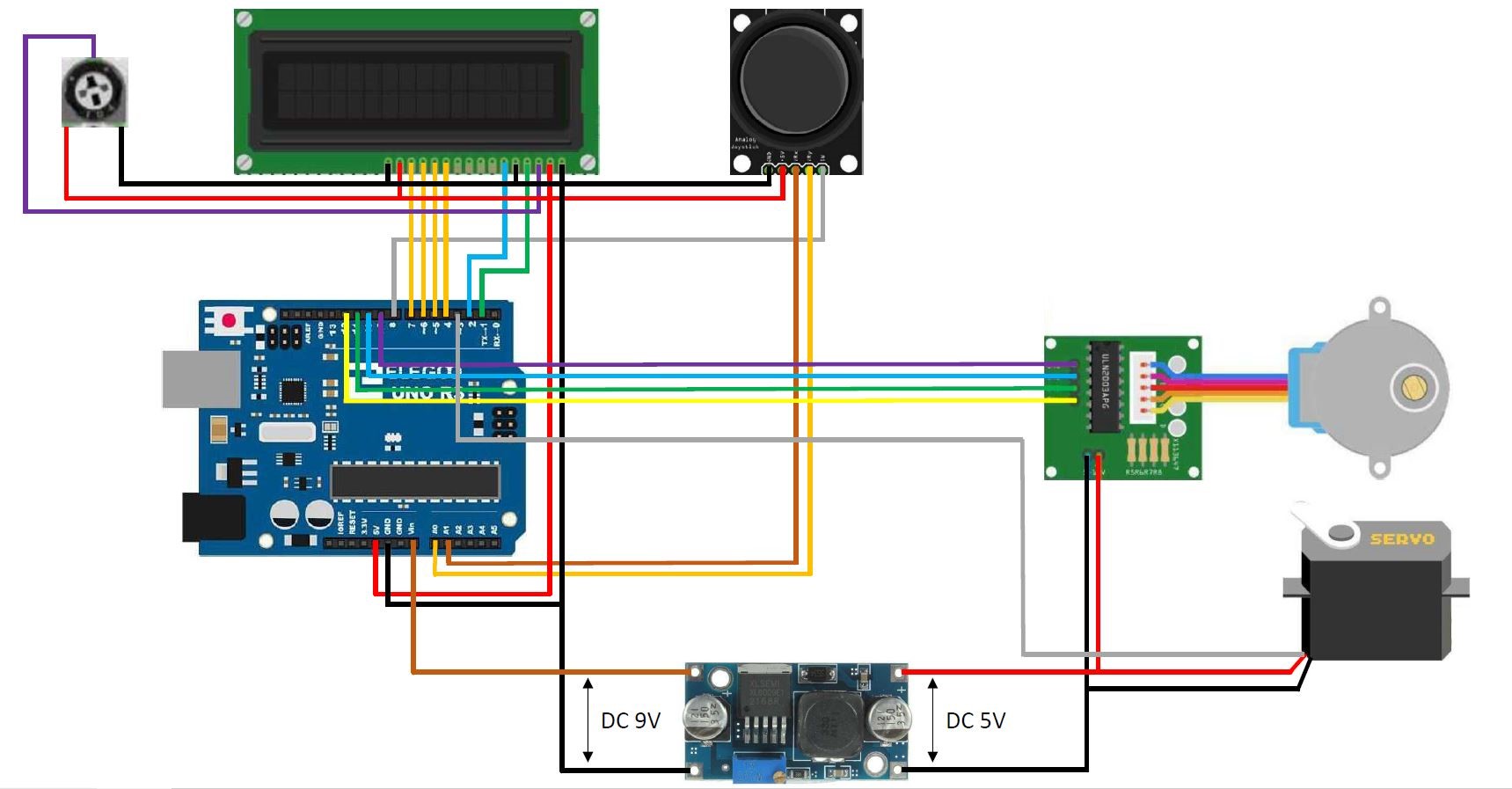
Once you have set up your Arduino board for 3D scanning, the next step is to wire the various components of your 3D scanner. Proper wiring ensures that the Arduino board can communicate with and control the scanner hardware effectively. Here are the general steps involved in wiring the 3D scanner components:
- Refer to Component Datasheets: Start by referring to the datasheets or technical documentation of the scanner components, including the laser module, camera, stepper motors, and motor drivers. These documents provide information on pin configurations, power requirements, and communication protocols.
- Identify Required Connections: Identify the necessary connections for each component based on the datasheet information. This may include connecting power and ground pins, digital or analog pins for data communication, and control pins for motor drivers.
- Prepare Wires and Connectors: Prepare the wires and connectors required for the connections. Ensure that you have wires of appropriate gauge and length to reach different components and connections. Strip the ends of the wires, tin them if necessary, and crimp or solder connectors as needed.
- Connect Power and Ground: Start by connecting the power and ground pins of the components. This typically involves connecting the positive (+) and negative (-) terminals of the power supply to the respective pins on the Arduino board, motor drivers, and other components.
- Connect Data and Control Pins: For communication between the Arduino board and the scanner components, connect the appropriate data and control pins. This may involve connecting digital pins, analog pins, or serial communication pins, depending on the requirements of your specific 3D scanner project.
- Wire Stepper Motors and Motor Drivers: Connect the stepper motors to the corresponding motor drivers. Ensure that the motor wiring follows the motor driver specifications, which typically include connections for separate coil phases and connections for power and ground.
- Double-Check Connections: Once all the connections are made, double-check the wiring to ensure that all connections are secure and in the correct positions. Ensure that there are no loose wires or short circuits that could potentially damage the components.
It is crucial to refer to the specific requirements and instructions provided by the manufacturer of your 3D scanner components. Always exercise caution when working with electrical connections and follow best practices to ensure safe and reliable operation of your 3D scanner.
Calibrating the 3D Scanner
Calibration is a critical step in the 3D scanning process as it ensures accurate and reliable measurements. Calibration involves aligning the scanner components, setting appropriate parameters, and compensating for any errors or distortions in the scanning system. Here are the steps to calibrate your 3D scanner:
- Positioning the Scanner: Start by positioning the 3D scanner and the scanned object in the desired configuration. Ensure that the object is placed on a stable surface and that the scanner has an unobstructed view of the object from different angles.
- Setting the Reference Point: Define a reference point or origin for your scanning system. This can be a specific location on the object’s surface where all subsequent measurements will be based. It is crucial to set a consistent reference point for accurate alignment and measurement.
- Calibrating the Sensor: Depending on the type of scanner technology, you may need to calibrate the sensors or cameras used in the scanning process. This involves adjusting parameters such as focus, exposure, or sensitivity to ensure optimal data collection and image quality.
- Aligning the Laser or Structured Light: If you’re using a laser or structured light scanner, it’s essential to align the emitted beam or pattern with the scanning system correctly. Make sure the laser or light source is perpendicular to the object’s surface and aligned with respect to the camera’s field of view.
- Compensating for Distortions: Scanning systems may introduce distortions or errors due to factors such as lens aberrations or geometric inaccuracies. To compensate for these distortions, you may need to apply correction algorithms or calibration matrices to the collected data during the scanning process.
- Performing Test Scans: Once the initial calibration is complete, perform a series of test scans using known objects or calibration targets. Use these scans to verify the accuracy and precision of your 3D scanner. Compare the acquired data with the known measurements to identify any systematic errors or variations.
- Iterative Refinement: Based on the results of your test scans, iteratively refine the calibration parameters and settings as needed. Repeat the calibration process and test scans until you achieve satisfactory results in terms of accuracy and precision.
- Documentation: Document the calibration process, including the specific parameter values, calibration methods used, and any adjustments made during the process. This documentation will be valuable for future reference and troubleshooting.
Calibration is an ongoing process, and it may need to be repeated periodically to account for changes in the scanning environment or system components. Regular calibration ensures the accuracy and reliability of your 3D scanner, allowing you to capture precise and high-quality 3D models of objects.
Programming the Arduino for 3D Scanning
Programming the Arduino board plays a crucial role in controlling the 3D scanner components and capturing the necessary data for 3D scanning. By writing code in the Arduino programming language, you can customize the scanning process, interface with the sensors and motors, and manage the flow of data. Here are the steps to program the Arduino for 3D scanning:
- Define Scanning Parameters: Begin by defining the scanning parameters in your code. This includes variables for the number of scans, scan resolution, scanning speed, and any other specific requirements for your scanning project. These parameters will depend on the characteristics of the object being scanned and the desired level of detail.
- Configure I/O Pins: Identify and configure the appropriate digital or analog pins on the Arduino for communicating with the scanner components. This may include pins for motor control, data acquisition from sensors or cameras, and signal control for the laser module or structured light projector.
- Implement Scanning Algorithm: Develop the scanning algorithm in your code. This algorithm will define the sequence of motor movements and data capture steps required to scan the object. It may involve controlling the stepper motors, triggering the data capture from sensors or cameras, and managing the data acquisition process.
- Data Processing: Define the necessary data processing steps in your code to structure and store the scanned data. This may include converting raw sensor data into meaningful measurements, aligning and merging multiple scans, and representing the data in a suitable format such as point clouds or meshes. Implement any necessary filtering or smoothing techniques to improve the quality of the scanned data.
- Error Handling: Incorporate error handling mechanisms in your code to handle unexpected events or errors during the scanning process. This may involve implementing checks for sensor errors, communication failures, or motor malfunctions. Include appropriate error messages or feedback to aid in debugging and troubleshooting.
- Testing and Iteration: Test your code with the actual hardware setup to ensure that it functions as intended. Monitor the motor movements, data acquisition, and any feedback from sensors or cameras to verify that the scanning process is successfully executed. Iterate and refine your code as necessary to improve performance and address any issues identified during testing.
- Code Documentation: Document your code to provide clear explanations of its functionality, including comments and relevant notes. This documentation can help you and others understand and maintain the code in the future, as well as facilitate troubleshooting and optimization.
By following these steps and utilizing the capabilities of the Arduino programming language, you can program your Arduino board to control the 3D scanner components and capture accurate and detailed 3D scans of objects.
Capturing 3D Scans with the Arduino and 3D Scanner
Once you have set up and programmed your Arduino board, you are ready to start capturing 3D scans with your 3D scanner. The Arduino acts as the brain of the scanning system, controlling the movement of the scanner components and coordinating the data capture process. Here are the steps involved in capturing 3D scans with the Arduino and 3D scanner:
- Prepare the Scanning Environment: Set up the scanning environment by ensuring adequate lighting and minimal interference. Clear the area of any obstacles or objects that may interfere with the scanning process. Position the scanner and the object to be scanned in the desired configuration.
- Power Up the System: Power up the Arduino board and verify that all the scanner components are properly connected and functioning. Ensure that the power supply is stable and providing the necessary voltage and current to all components.
- Initiate the Scanning Process: Trigger the scanning process by running the program you have uploaded to the Arduino. The program will execute the scanning algorithm, instructing the motor movements and data capture at each step.
- Movement and Data Capture: As the program runs, the Arduino will control the stepper motors to move the scanner or the object in a predetermined pattern. Simultaneously, it will trigger the data capture from the sensors or cameras, collecting the necessary information for each scan position.
- Combine Multiple Scans: If your scanning process involves capturing scans from multiple angles or positions, the Arduino will coordinate the movement and data capture sequence to ensure comprehensive coverage. It will align and merge the captured data to create a unified 3D scan of the object.
- Repeat and Refine: Depending on the level of detail and accuracy required, you may need to repeat the scanning process multiple times. This allows you to capture additional scans and refine the overall scan quality through post-processing techniques like averaging or noise reduction.
- Save and Store Data: Store the captured scan data in a suitable format, such as point clouds or mesh representations. Ensure that the storage format is compatible with the software you plan to use for post-processing and analysis.
- Review and Quality Control: After completing the scanning process, review the captured 3D scan data to identify any errors or anomalies. Perform quality control checks, such as checking for alignment issues, missing areas, or artifacts that may require further post-processing or re-scanning.
- Repeat or Move to Post-Processing: Based on the outcome of the review, you can repeat the scanning process if necessary or move on to post-processing to refine and optimize the captured scan data.
By following these steps, you can successfully capture 3D scans using the Arduino and 3D scanner. The Arduino’s control and coordination capabilities enable precise and systematic data capture, allowing you to create detailed and accurate 3D models of scanned objects.
Post-Processing the Scanned Data
Post-processing is a crucial step in the 3D scanning workflow as it involves refining and optimizing the captured scan data to create accurate and usable 3D models. Once you have captured the 3D scans using the Arduino and 3D scanner, you can apply various techniques and tools to enhance the quality and usability of the scanned data. Here are the steps involved in post-processing the scanned data:
- Data Cleaning: Start by cleaning the scanned data to remove any noise, outliers, or artifacts that may have been introduced during the scanning process. This can involve employing various filtering techniques, such as median filtering or statistical outlier removal, to improve the overall quality of the scan.
- Mesh Reconstruction: Convert the point cloud data generated by the scanning process into a mesh representation. This involves connecting the data points to create a surface mesh with faces and vertices. Depending on the software you are using, you may have options to adjust the mesh resolution, smoothness, and other parameters to optimize the final result.
- Mesh Refinement: Refine the generated mesh to remove any unwanted features or inconsistencies. This can include removing holes, filling gaps, or addressing any areas with poor surface quality. Consider applying techniques like mesh smoothing or surface reconstruction to achieve a more seamless and accurate representation of the scanned object.
- Textures and Colors: If your scanning process captured color or texture information, apply these to the mesh to add realism and detail to the 3D model. Use the captured color data to map onto the appropriate vertices or faces of the mesh, enhancing the visual appeal of the final model.
- Alignment and Registration: If you captured multiple scans from different angles or positions, align and register these scans to create a unified and complete 3D model. Use feature matching algorithms or manual alignment techniques to ensure that all scans are correctly merged, eliminating any misalignments or discontinuities.
- Smoothing and Optimization: Apply smoothing algorithms to reduce any surface imperfections or roughness in the final 3D model. Depending on the desired level of detail, you may also optimize the model for a specific purpose, such as reducing the polygon count for real-time applications or preparing the model for 3D printing.
- Exporting and File Formats: Once the post-processing is complete, export the final 3D model in a suitable file format that is compatible with your desired application or software. Common file formats for 3D models include STL, OBJ, or PLY, which can be used for further analysis, visualization, or fabrication.
- Quality Control and Iteration: Perform quality control checks on the post-processed 3D model to ensure accuracy and integrity. Verify the model against the original object or reference measurements to identify any discrepancies that may require iteration or refinement of the post-processing steps.
Applying these post-processing steps to the scanned data allows you to create high-quality and visually appealing 3D models. Remember that the specific post-processing techniques and tools may vary depending on the software you are using and the requirements of your project.
Conclusion
In conclusion, using a 3D scanner with Arduino opens up a world of possibilities for creating detailed and accurate 3D models of physical objects. With the right components, setup, and programming, you can capture the shape and geometry of objects and bring them into the digital realm.
Throughout this article, we have walked through the essential steps involved in using a 3D scanner with Arduino. From understanding what a 3D scanner is and how it works to setting up and wiring the components, calibrating the scanner, programming the Arduino, and capturing 3D scans, each step contributes to a successful scanning process.
By following a systematic approach, you can leverage the power of Arduino to control the movement of the scanner components, capture the necessary data, and create accurate 3D models. Post-processing the captured data allows you to refine the scans, remove any imperfections, and optimize the 3D models for various applications.
Whether you’re a hobbyist, student, or professional, learning how to use a 3D scanner with Arduino provides an avenue for creativity and innovation. You can explore diverse fields such as product design, animation, virtual reality, or even contribute to scientific research and documentation.
Keep in mind that the specific components, techniques, and software used may vary based on your project requirements and budget. It’s important to conduct thorough research, consult relevant resources, and experiment with different configurations to find the best setup for your needs.
With dedication and practice, you can master the art of 3D scanning with Arduino and unlock a whole new dimension of possibilities in the realm of digital design, fabrication, and visualization.