




Building your own MIDI keyboard is a practical weekend project that gives you a fully custom controller tailored to your playing style, and the core of the build is an Arduino board acting as the MIDI brain. This guide walks you through every step, from picking the right microcontroller to wiring a key matrix, adding faders, and testing your finished instrument, so you can build your own MIDI keyboard with confidence and without guesswork.
How to build your own MIDI keyboard: project overview
The goal is simple: create a USB MIDI controller that sends note-on, note-off, and control change messages to your computer or sound module. Instead of buying a commercial keyboard, you choose the keys, the number of octaves, and the knobs or sliders you want. An Arduino with native USB support handles the MIDI communication directly, so no extra interface hardware is needed. The project teaches you the fundamentals of matrix scanning, analog input, and MIDI protocol, all while producing an instrument you can actually play.
Choosing the right microcontroller and components
The most important decision is the microcontroller. For a plug-and-play USB MIDI experience, choose an Arduino board with a native USB port, such as the Leonardo, Micro, Zero, Due, 101, or Nano 33 IoT. These boards appear as a MIDI device when connected to a computer, eliminating the need for external drivers or bridge software. An older Arduino Uno requires flashing custom firmware onto its ATmega16U2 chip or using a serial-to-MIDI bridge like Hairless MIDI Serial Bridge and LoopMIDI, which adds complexity and latency. For most builders, a Leonardo or Micro is the sweet spot: they are inexpensive, widely available, and natively recognized as MIDI devices.
Beyond the board, gather these essential components:
- Key switches, tactile pushbuttons or mechanical keyboard switches, one per key.
- Diodes, one per key, typically 1N4148 or 1N4001, to prevent phantom key issues.
- Resistors, for pull-up or pull-down configurations on the matrix rows/columns.
- Jumper wires and a breadboard or perfboard for wiring.
- Potentiometers, rotary or sliding, for MIDI control change messages.
- Enclosure material, wood, acrylic, or 3D-printed parts.
- Arduino IDE installed on your computer, plus the MIDI USB library for native USB boards.
This component list is deliberately minimal. You can start with 12 keys (one octave) and expand later, or build a full 49-key controller if you have the patience and soldering skills.
Wiring the key matrix and diodes
A keyboard matrix circuit is the standard way to connect many switches with fewer pins. Instead of wiring each key to its own Arduino pin, you arrange the switches in rows and columns. For example, a 4x4 matrix handles 16 keys using only 8 pins. The Arduino scans each row and column combination to detect which key is pressed.
Each key switch must have a diode soldered in series with it, oriented so current flows from the column to the row. This diode is critical because it prevents phantom keys, unwanted notes that appear when multiple keys are pressed simultaneously. Without diodes, pressing three keys in an L-shape can falsely trigger a fourth key. The diode blocks that reverse current path, ensuring only the actual pressed keys register.
- Plan your matrix: decide rows and columns based on your key count.
- Place the switches in a grid on the breadboard or perfboard.
- Solder a diode to each switch, with the cathode (striped end) pointing toward the column line.
- Connect all switches in a row to a common row wire; connect all switches in a column to a common column wire.
- Connect each row wire to an Arduino digital pin, and each column wire to another digital pin.
- Add pull-up resistors on the row pins (10kΩ to 5V) or configure the pins with internal pull-ups in code.
Double-check every diode orientation before soldering. A reversed diode will cause that key to fail or behave erratically.
Adding potentiometers for MIDI control
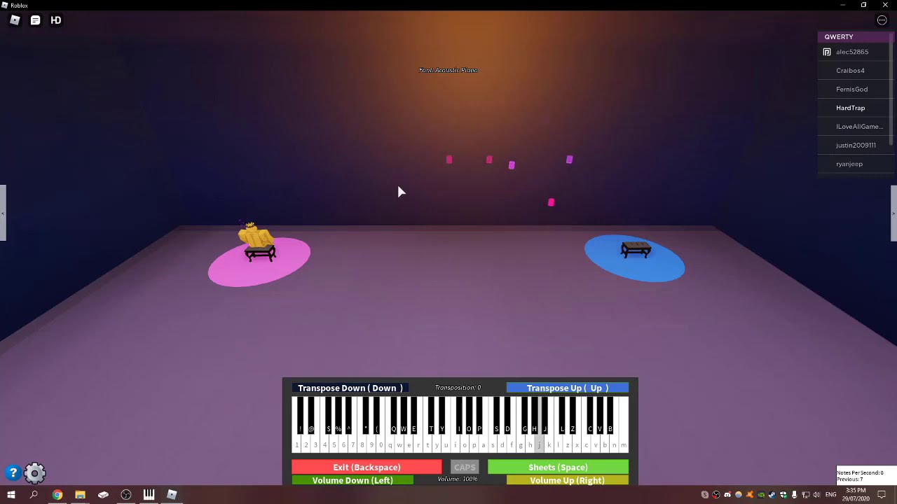
Potentiometers give your keyboard expressive control over parameters like volume, filter cutoff, or modulation depth. Connect each potentiometer to one of the Arduino’s analog input pins (A0, A5 on most boards). The wiper (middle pin) goes to the analog pin, and the outer pins connect to 5V and ground. The Arduino reads the voltage as a value from 0 to 1023, which you map to a MIDI control change value from 0 to 127. Once your hardware is sending MIDI, you can even connect a MIDI keyboard in Roblox to control in-game instruments with those same knobs.
Rotary potentiometers are great for knobs; sliding potentiometers (faders) are ideal for mixer-style volume control. You can add as many as you have free analog pins. Each one sends a MIDI Control Change (CC) message on a channel you assign in code. This lets you shape your sound in real time while playing.
Programming the Arduino MIDI firmware
With the hardware wired, the next step is writing the firmware. Install the Arduino MIDI USB library via the Library Manager in the Arduino IDE. This library handles the low-level USB MIDI communication, so your board appears as a MIDI device to your operating system.
The sketch does three things: scans the key matrix, debounces key presses, and sends MIDI messages. Here is the core logic:
- Define the row and column pins as arrays.
- Set row pins as inputs with internal pull-ups; set column pins as outputs.
- In the loop, drive each column low one at a time, then read all row pins.
- If a row reads low, that key is pressed. Compare against the previous state to detect changes.
- On a new press, send MIDI note-on with a velocity (e.g., 127). On release, send note-off.
- Read each analog pin; if the value changed by more than a small threshold, send a CC message with the mapped value.
Debouncing is essential, mechanical switches bounce for a few milliseconds. Add a 5-10 ms delay after detecting a state change, or use a debounce timer in code. Without it, you’ll get double-triggered notes.
Upload the sketch to your board, then open a MIDI monitor to see the messages streaming. If you see garbage or nothing, check your matrix wiring and diode orientation first.
Building an enclosure for your keyboard
A sturdy enclosure protects your electronics and makes the keyboard playable. The simplest option is a laser-cut wooden case: cut a top plate with holes for the keys and potentiometers, and a bottom box to hold the Arduino and wiring. Acrylic is another good choice, it’s transparent, so you can show off your build, and it cuts cleanly with a laser cutter. If you have a 3D printer, you can design a custom case with integrated key mounts and fader slots.
Whatever material you choose, plan the layout carefully. Leave enough space for the Arduino, wiring, and any connectors. Mount the key switches so they protrude through the top plate with a comfortable travel distance. Secure the potentiometers with their nuts and washers. Use standoffs to raise the Arduino off the bottom of the case, preventing short circuits against metal surfaces.
For a quick prototype, a shoebox or project box works fine. The goal is to keep all components fixed and the wiring tidy. You can always upgrade to a nicer enclosure later.
Testing and troubleshooting your MIDI keyboard
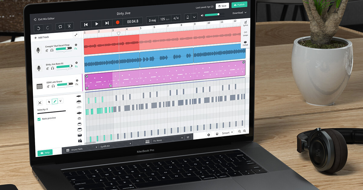
After uploading the code and closing the enclosure, test every function. Connect the keyboard to your computer and open a MIDI monitoring tool. On Windows, Virtual MIDI Piano Keyboard is a reliable choice; on Linux, use pw-mididump. These tools display incoming MIDI messages in real time, so you can verify that each key sends the correct note-on and note-off, and that each potentiometer sends CC messages with smooth values. Once everything checks out, you can use a MIDI keyboard in BandLab to start recording your ideas immediately, or use a MIDI keyboard with korg volca to sequence its analog synth engine directly.
Start by pressing each key individually. Confirm the note number matches your intended layout. Then press multiple keys simultaneously to check for phantom keys, if you see extra notes, your diodes are missing or reversed. Next, move each potentiometer through its full range. The CC value should sweep from 0 to 127 without jumps or dropouts. If a fader jumps erratically, check the wiring and ensure the wiper is connected to the analog pin.
Common issues and fixes:
- No MIDI output at all: verify the board is a native USB MIDI model, and that the MIDI USB library is installed.
- Some keys don’t work: check the row/column pin assignments in code against your wiring.
- Phantom keys: confirm every diode is oriented correctly (cathode toward the column).
- Notes stuck on: the key release isn’t detected. Check for cold solder joints on that switch.
- Potentiometer jitter: add a small delay (10 ms) between analog reads and only send when the value changes by more than 2-3 units.
Take your time with this phase. A thorough test now saves hours of frustration later when you’re trying to record a take and a key misfires. Once everything checks out, your custom MIDI keyboard is ready for music production, live performance, or sound design, a one-of-a-kind instrument built entirely by you.