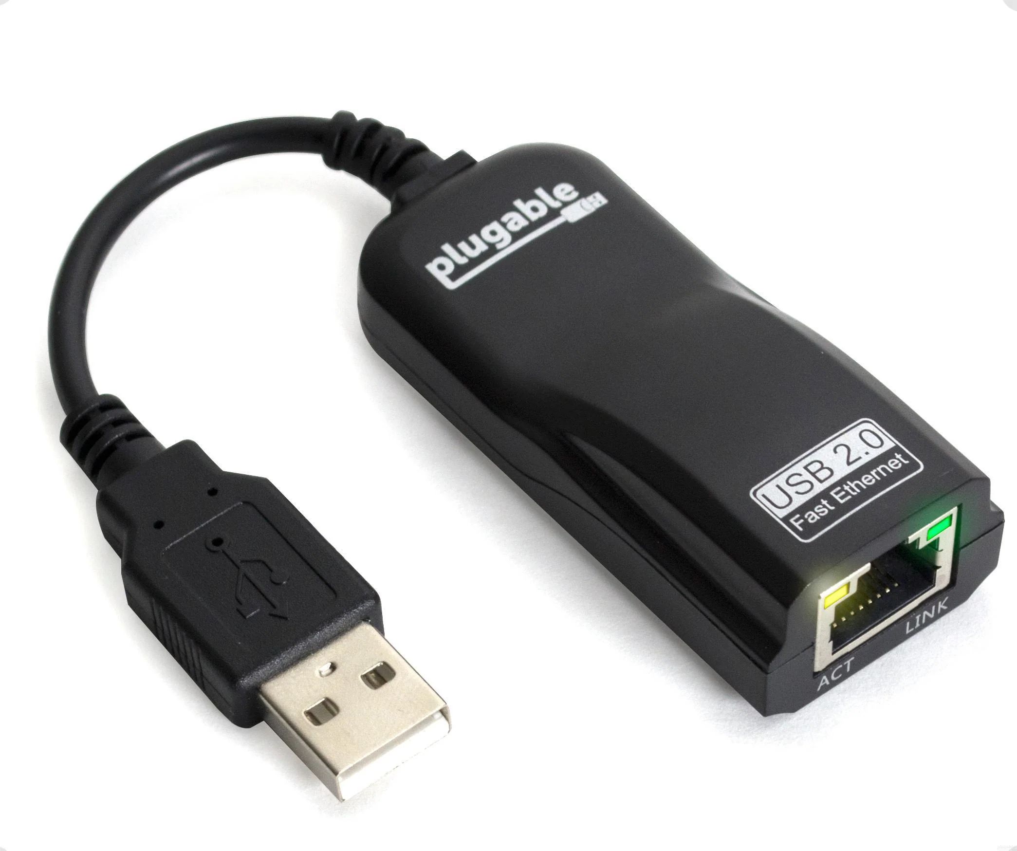
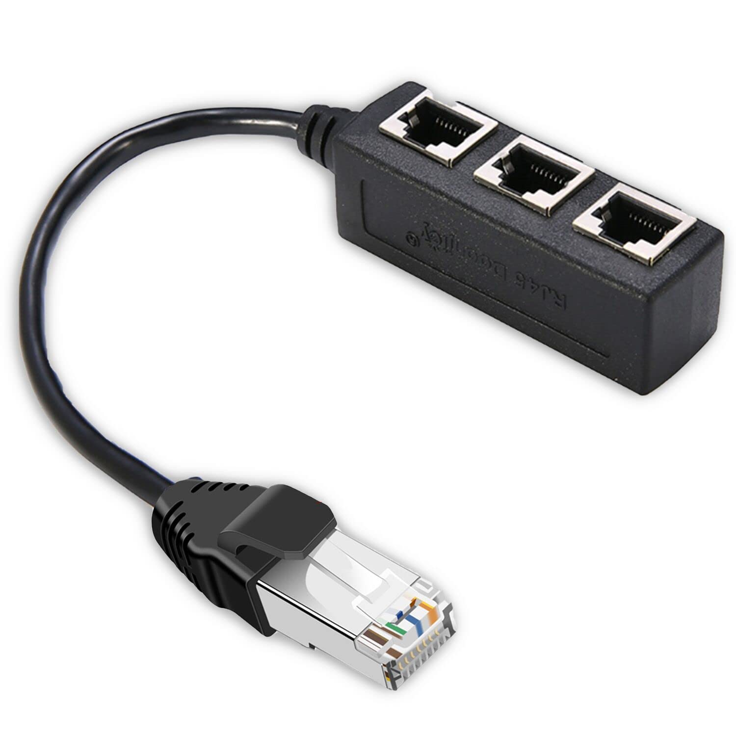
What is an Ethernet Switch?
An Ethernet switch is a networking device that connects multiple devices in a local area network (LAN) and facilitates the communication between them. It works at the data link layer of the OSI model and helps to transmit data efficiently and securely across the network.
Unlike a hub, which broadcasts data packets to all connected devices, an Ethernet switch intelligently directs the data packets to their intended destination. This makes the switch more efficient and ensures faster communication by avoiding unnecessary network traffic.
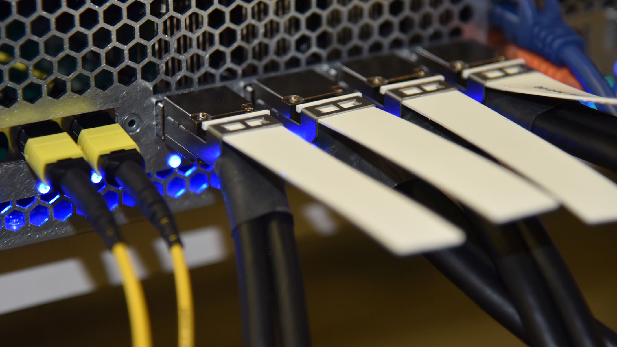
Switches come in various sizes, from small switches designed for home networks to large enterprise-grade switches that can handle extensive data traffic. They consist of multiple Ethernet ports that enable connections with computers, printers, servers, and other network devices.
Moreover, Ethernet switches support different data transfer speeds, such as 10/100/1000 Mbps, or even higher for advanced switches. This allows for flexibility in handling different network requirements, from basic internet browsing to streaming high-definition videos or supporting bandwidth-intensive applications.
Another key feature of an Ethernet switch is its ability to support Power over Ethernet (PoE). This technology allows the switch to provide electrical power to PoE-enabled devices, such as IP cameras, VoIP phones, or wireless access points. This eliminates the need for separate power cables, simplifying the installation process.
In summary, an Ethernet switch plays a crucial role in network infrastructure by efficiently managing and directing data traffic. It provides a reliable and secure means of communication between devices within a LAN and ensures that data packets reach their intended destinations quickly and accurately.
How Does an Ethernet Switch Work?
An Ethernet switch operates by analyzing data packets received on each of its ports and forwarding them to the appropriate destination. It uses the Media Access Control (MAC) addresses of devices to determine where the packets need to be sent.
When a device connected to an Ethernet switch sends data, the switch examines the MAC address of the source device and adds it to its internal memory, known as a forwarding table. This table keeps track of the MAC addresses of devices connected to each port of the switch.
When a packet is received, the switch looks up the destination MAC address in its forwarding table to determine the appropriate port to send the packet. If the switch doesn’t have the destination MAC address in its memory, it will flood the packet to all ports except for the one it was received on. This ensures that the packet reaches the destination device, which will then respond and update the switch’s forwarding table with its MAC address.
An Ethernet switch also differentiates between broadcast, unicast, and multicast traffic. Broadcast traffic is sent to all devices in the network, while unicast traffic is sent to a specific device. Multicast traffic is sent to a group of devices that have joined a multicast group.
Moreover, VLANs (Virtual Local Area Networks) can be configured on an Ethernet switch. VLANs allow networks to be divided into logical segments, which can improve network performance, security, and management. Trunking, also known as link aggregation, enables multiple physical links between switches to be combined into a single logical link, increasing bandwidth and providing redundancy.
In addition, managed switches offer advanced features and configurations, such as Quality of Service (QoS) settings to prioritize certain types of traffic, and Spanning Tree Protocol (STP) to prevent loops in the network, ensuring redundant paths while avoiding network disruptions.
Overall, an Ethernet switch is a critical component in a network infrastructure, facilitating efficient and secure communication between devices. Its ability to analyze and forward data packets based on MAC addresses ensures that data reaches its intended destination accurately and in a timely manner.
The Basics of Ethernet Switching
Ethernet switching is the process by which an Ethernet switch forwards data packets between devices connected to its ports. Understanding the basics of Ethernet switching is essential for managing and optimizing network performance.
At its core, Ethernet switching is based on the concept of broadcasting and learning. When a device connected to a switch sends a data packet, the switch examines the source MAC address of the packet and updates its forwarding table, associating the MAC address with the corresponding port.
The forwarding table is crucial in Ethernet switching as it maps MAC addresses to specific ports on the switch. This helps the switch intelligently direct incoming packets to their intended destinations, rather than broadcasting them to all connected devices.
When a switch receives a packet, it looks up the destination MAC address in its forwarding table. If it finds a matching entry, it forwards the packet only to the port associated with that MAC address. This process is known as unicast traffic forwarding, ensuring that packets are delivered directly to their intended recipients.
If the switch doesn’t have an entry for the destination MAC address in its forwarding table, it engages in flooding. Flooding means the switch broadcasts the packet to all ports, except for the port it received the packet on. This ensures that the packet reaches the intended device, which will then respond and update the switch’s forwarding table accordingly.
Ethernet switching also involves handling broadcast and multicast traffic. When a switch receives a broadcast packet, it forwards the packet to all connected devices, ensuring that every device in the network receives the broadcast message. This is essential for protocols like Address Resolution Protocol (ARP), which allows devices to discover MAC addresses.
Similarly, multicast traffic is sent to a specific group of devices that have joined a multicast group. A switch uses multicast forwarding entries in its forwarding table to determine which ports should receive the multicast traffic.
Overall, Ethernet switching forms the backbone of modern LAN networks, allowing devices to communicate efficiently. By using forwarding tables and intelligently directing traffic based on MAC addresses, switches minimize network congestion, improve performance, and provide a secure and reliable means of data transmission.
Learning and Forwarding Tables
In Ethernet switching, learning and forwarding tables play a crucial role in determining how data packets are forwarded within a network. Understanding these concepts helps in optimizing network performance and ensuring efficient data transmission.
When a switch receives a data packet, it examines the source MAC address of the packet and updates its learning table, also known as a MAC address table or forwarding table. The learning table maps MAC addresses to specific switch ports, associating each MAC address with the port on which the packet was received.
By continuously updating the learning table, a switch builds a database that allows it to intelligently forward incoming packets to their intended destinations. This process is known as MAC address learning.
When a switch receives a packet with a destination MAC address, it looks up the MAC address in its learning table. If a matching entry is found, the switch forwards the packet only to the port associated with that MAC address. This process is known as unicast forwarding.
If the switch doesn’t have an entry for the destination MAC address in its learning table, it engages in flooding. Flooding means the switch broadcasts the packet to all ports, except for the port it received the packet on. This ensures that the packet reaches the intended device, which will then respond and update the switch’s learning table accordingly.
Forwarding tables, on the other hand, determine how packets are forwarded based on the entries in the learning table. A forwarding table is a key component in an Ethernet switch as it maps MAC addresses to specific ports, enabling the switch to efficiently direct traffic and avoid unnecessary broadcasts.
It’s important to note that forwarding tables have a limited size, so switches need to have mechanisms to handle situations where the table is full. One common approach is to use aging timers, where the switch regularly removes entries from the table that have not been used recently.
Furthermore, forwarding tables can be dynamic or static. Dynamic forwarding tables are automatically updated through the MAC address learning process. Static forwarding tables, on the other hand, are manually configured by network administrators, specifying the MAC address and corresponding switch port for each entry.
By combining MAC address learning with forwarding tables, Ethernet switches can efficiently handle data traffic within a network. The learning process allows switches to dynamically update their forwarding tables, ensuring that packets are delivered accurately and reducing unnecessary network congestion.
Unicast, Broadcast, and Multicast Traffic Handling
In Ethernet switching, handling different types of traffic is essential for efficient communication within a network. Unicast, broadcast, and multicast traffic are the three main categories of traffic that Ethernet switches need to effectively manage.
Unicast traffic refers to a one-to-one communication, where a packet is sent from a source device to a specific destination device. When an Ethernet switch receives a unicast packet, it checks the destination MAC address in its forwarding table and forwards the packet only to the port associated with that MAC address. This ensures that the packet reaches its intended recipient directly and efficiently.
Broadcast traffic, on the other hand, is a one-to-all communication, where a packet is sent to all devices within a network. Broadcast traffic is typically used for protocols such as Address Resolution Protocol (ARP) or for broadcasting important notifications to all network devices. When an Ethernet switch receives a broadcast packet, it floods the packet to all ports, except for the port it was originally received on. This ensures that all devices within the network receive the broadcast message.
Multicast traffic, unlike unicast and broadcast, is a one-to-many communication, where a packet is sent to a group of devices that have joined a multicast group. Multicast traffic is commonly used for applications like video streaming, online gaming, or live audio transmissions. To handle multicast traffic, switches utilize multicast forwarding entries in their forwarding tables. These entries specify the ports to which the multicast packets should be forwarded. By using multicast forwarding entries, switches ensure that the multicast traffic is only sent to the devices interested in receiving it, minimizing unnecessary network traffic.
It’s worth noting that managing broadcast and multicast traffic is crucial for maintaining network efficiency. If a switch were to flood every broadcast or multicast packet to all connected devices, it could quickly lead to congestion on the network. By intelligently handling these types of traffic, Ethernet switches optimize network performance and bandwidth utilization.
Overall, Ethernet switches play a vital role in handling unicast, broadcast, and multicast traffic within a network. By efficiently forwarding unicast traffic based on MAC addresses, flooding broadcast traffic to all devices, and selectively forwarding multicast traffic based on multicast group memberships, switches ensure effective communication and minimize unnecessary network congestion.
VLANs and Trunking
VLANs (Virtual Local Area Networks) and trunking are two crucial concepts in Ethernet switching that offer enhanced network segmentation and flexibility. Understanding how VLANs and trunking work can greatly improve network management and security.
A VLAN is a logical partition within a physical network, allowing devices to be grouped together based on characteristics such as department, function, or security requirements. VLANs provide several benefits, including improved network performance, simplified network management, and strengthened network security.
With VLANs, a single physical switch can be divided into multiple virtual switches, each representing a different VLAN. Devices within the same VLAN can communicate with each other as if they were connected to the same physical LAN, even if they are located across different switches or networks.
When a switch receives a packet, it examines the VLAN tag in the packet header to determine the appropriate VLAN. Based on the VLAN tag, the switch forwards the packet only to the ports associated with that VLAN, ensuring that the packet remains within the intended VLAN network.
Trunking, also known as link aggregation, allows multiple physical links between switches to be combined into a single logical link. This provides increased bandwidth and redundancy by balancing traffic across these links.
Trunking is achieved by utilizing a networking protocol called IEEE 802.1Q. This protocol adds a VLAN tag to each packet, indicating the VLAN to which the packet belongs. This allows switches to identify and correctly route the packets through the trunk link.
Trunking is particularly useful in situations where VLANs need to be extended across multiple switches or to connect switches to routers or servers that support multiple VLANs. It reduces the need for separate physical connections for each VLAN and simplifies network configuration and management.
In addition, trunking enables the transmission of different VLANs over a single physical connection, facilitating efficient utilization of network resources and reducing costs.
By using VLANs and trunking, network administrators can achieve better network segmentation, isolate network traffic, and improve network performance. VLANs provide increased security by preventing unauthorized access to sensitive data and by controlling traffic flow within the network.
In summary, VLANs and trunking are essential features of Ethernet switching that enable network segmentation, improved performance, and enhanced security. VLANs allow logical grouping of devices, while trunking provides a way to efficiently transmit multiple VLANs over a single physical connection.
Link Aggregation
Link aggregation, also known as port aggregation or bonding, is a technique used in Ethernet switching to combine multiple physical links between switches or devices into a single logical link. Link aggregation offers several benefits, including increased bandwidth, improved fault tolerance, and enhanced network performance.
With link aggregation, multiple physical links, also known as member links or constituent links, are grouped together to form a link aggregation group (LAG). This LAG functions as a single, high-bandwidth link, allowing for the efficient utilization of network resources.
The IEEE 802.3ad standard defines the Link Aggregation Control Protocol (LACP), which is commonly used for negotiating and managing link aggregation between switches or devices. LACP enables dynamic formation and maintenance of link aggregation groups, ensuring optimal utilization of the available links.
Link aggregation provides increased bandwidth by allowing traffic to be distributed across multiple member links. By balancing traffic across the links, link aggregation minimizes bottlenecks and congestion, resulting in improved network performance and faster data transmission rates.
In addition to increased bandwidth, link aggregation also offers improved fault tolerance. If one member link within a link aggregation group fails or experiences issues, the traffic is automatically rerouted through the remaining operational member links. This redundancy ensures uninterrupted connectivity and minimizes network downtime.
Furthermore, link aggregation provides load balancing, spreading traffic evenly across the available member links. This load balancing mechanism allows for better utilization of network resources and prevents individual links from becoming overloaded, further enhancing network performance.
Link aggregation can be implemented between switches, between a switch and a server, or even between switches from different vendors, as long as they support the same link aggregation protocol. This flexibility enables businesses to customize their network infrastructure based on their specific needs and requirements.
It’s important to note that link aggregation requires compatible equipment and configuration on both ends of the aggregated link. Additionally, the switch or device receiving the aggregated link must be able to support link aggregation and distribute the traffic across the member links effectively.
In summary, link aggregation is a powerful technique in Ethernet switching that allows for the efficient utilization of multiple physical links. By providing increased bandwidth, improved fault tolerance, and load balancing capabilities, link aggregation enhances network performance and reliability, making it an invaluable feature in modern network environments.
Quality of Service (QoS)
Quality of Service (QoS) is a feature in Ethernet switching that enables network administrators to prioritize certain types of network traffic to ensure optimal performance for critical applications. QoS helps manage network congestion, reduce latency, and provide a consistent user experience.
With QoS, network administrators can assign different levels of priority to different types of traffic, ensuring that bandwidth is allocated appropriately based on the specific requirements of each application or service.
QoS works by examining certain characteristics of network traffic, such as source/destination IP addresses, protocol types, or DiffServ Code Points (DSCP) values, and then applying specific actions to prioritize or control the flow of traffic.
One common QoS technique used in Ethernet switching is traffic classification. Traffic classification involves categorizing network traffic into various classes based on its importance or characteristics. For example, voice or video traffic might be assigned a higher priority than ordinary data traffic.
Another key aspect of QoS is traffic shaping or traffic policing. Traffic shaping involves buffering and regulating network traffic to ensure that it adheres to predefined bandwidth limits. Traffic policing, on the other hand, enforces bandwidth limits by discarding or remarking packets that exceed the permitted bandwidth.
QoS also enables the use of priority queues, where traffic is segregated into different queues based on its priority level. This allows high-priority traffic to be processed and transmitted with minimal delay, ensuring a smooth and uninterrupted user experience for critical applications.
Furthermore, QoS techniques such as packet scheduling and queuing algorithms help manage network congestion during periods of high traffic load. These techniques prioritize time-sensitive packets, such as VoIP or video streaming packets, to reduce latency and maintain reliable communication.
Implementing QoS on Ethernet switches requires careful planning and configuration to ensure that the desired QoS policies are applied effectively. It is important to identify the critical applications and user requirements, understand the network traffic patterns, and define appropriate QoS policies accordingly.
Overall, QoS is an integral feature in Ethernet switching that allows network administrators to optimize network performance and provide enhanced service quality for critical applications. By prioritizing and managing network traffic, QoS helps reduce latency, improve reliability, and ensure a consistent user experience even in high-traffic environments.
Spanning Tree Protocol (STP)
The Spanning Tree Protocol (STP) is a network protocol used in Ethernet switching to prevent network loops and ensure the redundancy of network links without creating broadcast storms or data collisions. STP creates a loop-free topology in network infrastructure by blocking redundant paths while maintaining alternative active paths.
STP operates by designating one switch as the root bridge and then calculating the shortest path to the root bridge for each switch in the network. The root bridge serves as the central point for the network, and all data traffic is directed through the root bridge and along the shortest path.
When multiple paths are available between switches, STP determines the least-cost path by assigning path costs to each link. The path cost is based on the link speed, with higher bandwidth links having lower costs. This ensures that traffic flows through the most efficient links in the network.
STP also uses a process called bridge protocol data units (BPDU) exchange to exchange information and communicate between switches in the network. BPDUs are messages that contain information about the switch, such as its bridge ID and path cost, and they are used by switches to negotiate and establish the best paths to the root bridge.
In the event of a link failure or the addition of a new link, STP recalculates the topology and adjusts the active and blocked ports to adapt to the changes. This ensures that the network remains stable and operational even in the presence of network changes.
By blocking redundant paths, STP prevents loops in the network that can result in broadcast storms and data collisions. Loops occur when there are multiple active paths between switches, causing packets to cycle endlessly and congest the network. STP eliminates these loops by keeping one active path and disabling the others.
STP has evolved over time, with enhancements such as Rapid Spanning Tree Protocol (RSTP) and Multiple Spanning Tree Protocol (MSTP) introduced to improve convergence time and scalability.
It’s important to note that STP convergence time, the time taken for the network to stabilize after a change, can vary, leading to potential temporary network disruptions. Network administrators should carefully plan and configure STP parameters to minimize the impact of convergence time on network performance.
In summary, Spanning Tree Protocol (STP) is a crucial network protocol in Ethernet switching that prevents loops and ensures redundancy in network infrastructure. By calculating the shortest path to the root bridge, blocking redundant paths, and adapting to network changes, STP maintains a stable and loop-free network topology.
Power over Ethernet (PoE)
Power over Ethernet (PoE) is a technology used in Ethernet switching that allows electrical power to be transmitted along with data over standard Ethernet cables. PoE eliminates the need for separate power cables, simplifying the installation and deployment of network devices.
With PoE, devices such as IP cameras, VoIP phones, wireless access points, and IoT devices can be powered directly through the Ethernet cable, using power sourced from the Ethernet switch or PoE injector. This eliminates the need for individual power adapters and electrical power outlets near each device.
PoE operates by leveraging unused pairs of wires within the Ethernet cable to transmit low-voltage DC power. This is achieved by introducing power sourcing equipment (PSE) in the form of a PoE-enabled switch or injector, and powered devices (PD) that receive power from the PSE within the Ethernet cable.
There are different PoE standards, such as IEEE 802.3af, which provides up to 15.4 Watts of power per port, and IEEE 802.3at, also known as PoE+, which delivers up to 30 Watts of power per port. These standards enable a variety of devices to be powered over Ethernet, from low-power devices like VoIP phones to high-power devices like Pan-Tilt-Zoom (PTZ) cameras.
PoE has several advantages beyond simplified installation. It enables remote power management, allowing network administrators to monitor and control the power consumption of PoE devices. It also provides flexibility in device placement, as PoE devices can be installed in locations without access to power outlets.
Additionally, PoE supports power management protocols, such as Power over Ethernet Plus (PoE+) and Intelligent Power Management (IPM), that enable intelligent power allocation and negotiation between the PSE and PD. This ensures efficient power usage and protects devices from potential power overloads.
It’s worth noting that not all network switches are PoE-enabled. It is essential to check the specifications of the switch and the power requirements of the devices to ensure compatibility and proper power delivery.
With the increasing popularity of PoE, the technology has evolved to include features like PoE pass-through for powering multiple devices in a daisy-chain, PoE extenders for extending power and data transmission distances, and PoE+, which provides higher power output for devices with greater power requirements.
In summary, Power over Ethernet (PoE) is a convenient and efficient technology that allows for the transmission of both data and power over Ethernet cables. PoE simplifies installation, enables remote power management, and provides flexibility in device placement, making it a valuable feature in Ethernet switching.
Managed vs. Unmanaged Switches
Managed and unmanaged switches are two categories of Ethernet switches that offer different levels of control, management, and flexibility. Understanding the differences between these types of switches is key to selecting the right one for your network needs.
An unmanaged switch is a plug-and-play device that requires no configuration or management. It is designed for basic network connectivity, providing the essential function of forwarding data packets between devices connected to its ports. Unmanaged switches are typically used in small home or office networks where simplicity and ease of use are the main priorities.
Unmanaged switches have a fixed set of features and operate with default settings. They do not offer advanced configuration options or monitoring capabilities. This makes them simple and straightforward to use, but it also limits their flexibility and control over the network.
On the other hand, managed switches offer a higher level of control and customization. They provide extensive management capabilities that allow network administrators to configure and monitor network settings, prioritize traffic, and apply security measures.
Managed switches offer a web-based or command-line interface (CLI) through which administrators can access and configure various features and settings. This includes managing VLANs, configuring link aggregation, implementing Quality of Service (QoS) policies, setting up access control lists (ACLs), and monitoring network performance.
With managed switches, administrators have granular control over the network, allowing them to optimize performance, improve security, and troubleshoot issues effectively. These switches are commonly used in large-scale enterprise networks, where the ability to manage and control the network is essential.
Managed switches also offer features like SNMP (Simple Network Management Protocol) support, which allows for network monitoring and management from a centralized network management system. This enables administrators to gather information, detect issues, and remotely configure managed switches in the network.
However, the advanced features and management capabilities of managed switches come at a higher cost and require more expertise to set up and maintain. They entail additional effort and time investment in configuration and monitoring activities.
In summary, the choice between managed and unmanaged switches depends on the specific requirements of the network. Unmanaged switches are simple, plug-and-play devices that provide basic connectivity, while managed switches offer advanced configuration options, monitoring capabilities, and greater control over the network. Consider the size, complexity, and management needs of your network to determine which type of switch is best suited for your environment.
Conclusion
Ethernet switches are essential networking devices that facilitate the communication between devices within a local area network (LAN). They play a crucial role in managing and directing data traffic, ensuring efficient and secure transmission of data.
Throughout this article, we have explored various aspects of Ethernet switching, including the basics of how switches work, the importance of learning and forwarding tables, and how switches handle different types of network traffic.
We have also discussed the significance of VLANs and trunking in network segmentation and flexibility, as well as the benefits of link aggregation in increasing bandwidth and improving fault tolerance. Furthermore, we delved into the concept of Quality of Service (QoS) and the role it plays in prioritizing network traffic to ensure optimal performance for critical applications.
We also explored the Spanning Tree Protocol (STP) and its ability to prevent network loops and maintain a stable network topology. Additionally, we discussed Power over Ethernet (PoE) and how it simplifies device installation and provides power to network devices through the Ethernet cable.
Lastly, we compared managed and unmanaged switches, highlighting the differences in control, management, and customization between these two types of switches.
Understanding the intricacies of Ethernet switching is vital for network administrators and IT professionals to effectively manage and optimize their networks. Whether it’s configuring VLANs for network segmentation, implementing QoS policies for prioritizing specific traffic, or utilizing link aggregation for increased bandwidth, a solid knowledge of Ethernet switching ensures the smooth and reliable operation of network infrastructure.
By staying informed about the latest advancements and best practices in Ethernet switching, network administrators can make informed decisions, enhance network performance, and adapt to the evolving needs of their networks.
In conclusion, Ethernet switching is a fundamental aspect of network infrastructure, enabling efficient communication and data transmission within local area networks. With its continuous evolution and advancements, Ethernet switching continues to play a crucial role in the ever-expanding world of networking.


