Introduction
Welcome to the world of RFID (Radio Frequency Identification) tags! In this article, we will guide you through the process of making your very own RFID tag. RFID technology is becoming increasingly popular in various industries, from access control and inventory management to tracking and identification systems.
RFID tags are small electronic devices that use radio waves to transmit data wirelessly. These tags consist of a microchip attached to an antenna, which enables communication with RFID readers. They can be used to store and retrieve information, making them ideal for applications that require efficient and accurate data collection.
Creating your own RFID tag can be a fun and educational project. By understanding the components and circuitry involved, you can gain valuable knowledge about how this fascinating technology works. Plus, it’s a great way to showcase your DIY skills and impress your friends!
In this tutorial, we will provide a step-by-step guide to creating an RFID tag. We will start by discussing the necessary components and sharing a circuit diagram. Then, we will walk you through the process of gathering the materials, setting up the circuit, programming the Arduino, assembling the RFID tag, and finally, testing its functionality.
By the end of this tutorial, you will have a functioning RFID tag that can be used for various purposes. Whether you want to experiment with access control systems, build an inventory tracking solution, or simply explore the possibilities of RFID technology, this project will equip you with the necessary knowledge and skills.
So, let’s dive in and embark on this exciting journey of creating your very own RFID tag!
What is an RFID Tag?
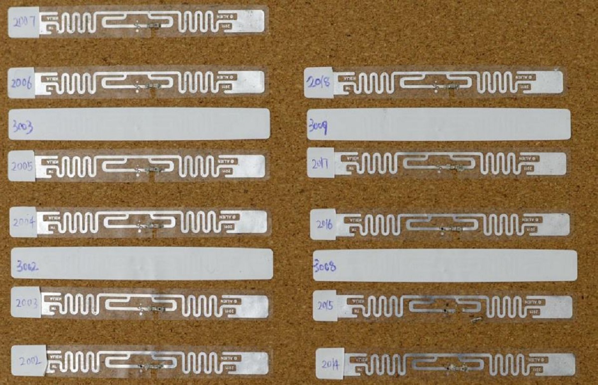
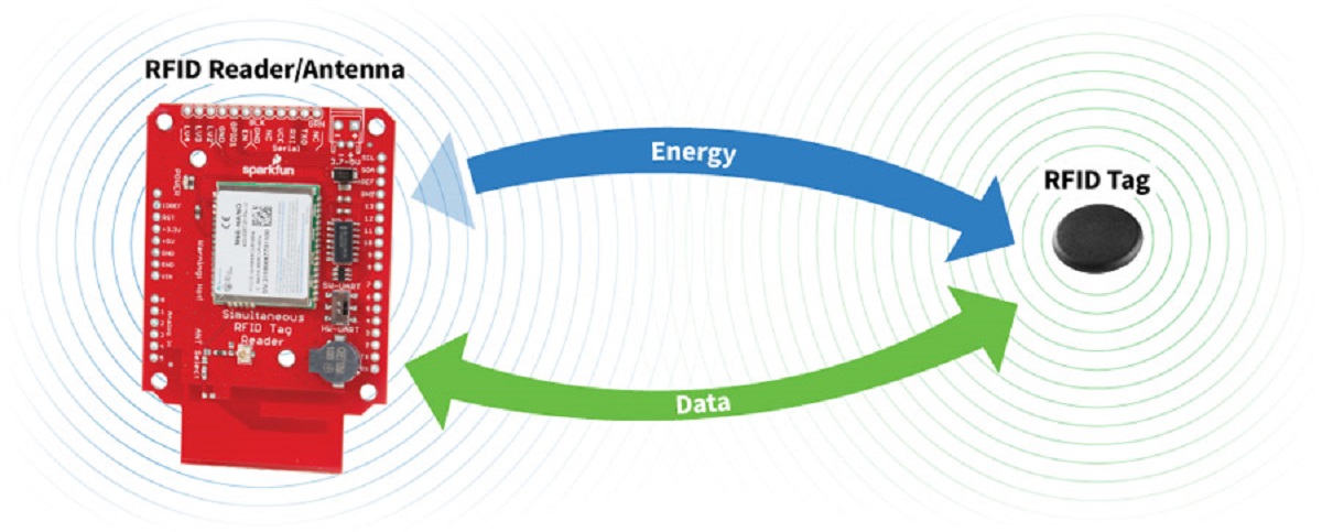
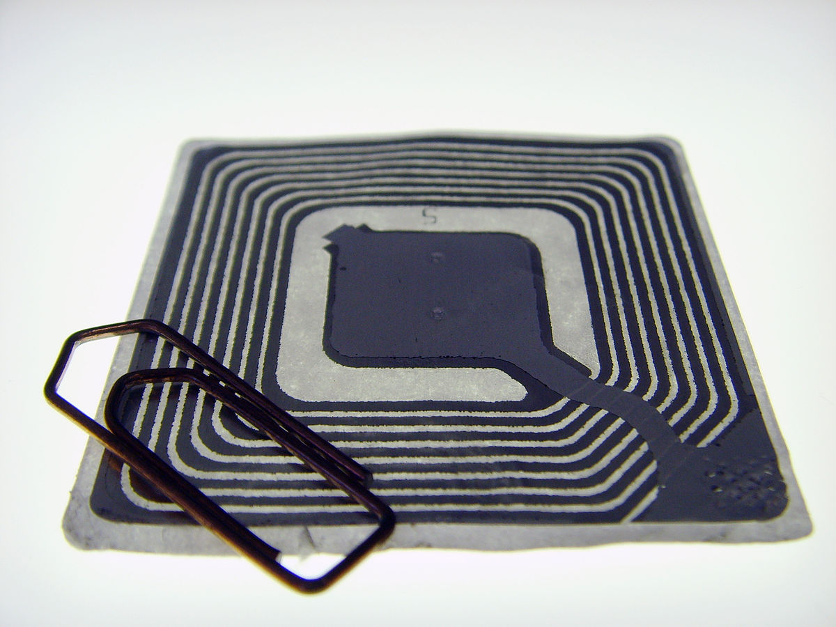
An RFID (Radio Frequency Identification) tag is a small electronic device that uses radio waves to transmit and receive data wirelessly. It consists of a microchip and an antenna, which are attached together to form a compact unit. The microchip stores information, while the antenna enables communication with RFID readers.
RFID tags are commonly used in various industries and applications. They can be found in access control systems, inventory management systems, transportation and logistics, healthcare, and even in our everyday lives. You may already encounter RFID technology in the form of key cards for building access or even in the tags attached to items in a retail store.
One of the unique features of RFID tags is their ability to be read and written to without direct physical contact. This means that the reader can communicate with the tag even if it is hidden inside an object or embedded within a surface. This makes them highly suitable for applications where manual scanning or input is not feasible.
RFID tags come in different forms, including passive, active, and semi-passive tags. Passive tags do not have an internal power source and rely on the energy received from the reader to operate. Active tags have their own power source and can transmit data over longer distances. Semi-passive tags combine the features of both passive and active tags.
The applications of RFID tags are diverse. In access control systems, RFID tags are used to grant or restrict access to specific areas, replacing traditional key-based systems. In inventory management, RFID tags enable accurate and efficient tracking of goods, reducing time spent on manual inventory counts. They can also be used in transportation and logistics to track shipments, ensuring their secure and timely delivery.
With advancements in technology, RFID tags are becoming more affordable and accessible, allowing for broader adoption across industries. By understanding the fundamentals of RFID technology and learning how to create your own RFID tag, you can unlock a world of possibilities and explore the potential applications of this versatile technology.
Components Required
Before you start building your RFID tag, let’s gather all the necessary components. Here’s a list of the components you will need:
- Arduino board: This is the brain of the RFID tag. You can use an Arduino Uno or any compatible board.
- RFID module: Look for an RFID module that supports your desired frequency, such as 125kHz or 13.56MHz.
- RFID tags: You will need a batch of RFID tags that are compatible with your RFID module. Make sure to get enough tags for your project.
- Jumper wires: These wires will be used to connect the RFID module to the Arduino board and other components.
- Breadboard: A breadboard will provide a convenient platform for prototype development. It will allow you to connect and disconnect components without soldering.
- Resistors: Depending on the RFID module you choose, you may need resistors to ensure proper voltage and current levels.
- LED (optional): If you want to add a visual indicator to your RFID tag, you can include an LED and a corresponding resistor.
It’s important to ensure that all the components you choose are compatible with each other and meet your project requirements. Check the specifications of the RFID module and Arduino board to confirm their compatibility.
Once you have gathered all the necessary components, you are ready to proceed to the next step: setting up the circuit. In the next section, we will discuss the circuit diagram and guide you through the process of connecting the components.
Circuit Diagram
Now that you have all the required components, it’s time to set up the circuit for your RFID tag. Follow the circuit diagram below to connect the components correctly:


Here’s a brief explanation of the connections in the circuit diagram:
- Arduino and RFID module: Connect the Arduino’s 5V pin to the RFID module’s VCC pin, the Arduino’s GND pin to the RFID module’s GND pin, and the Arduino’s digital pins to the RFID module’s SDA and SCK pins. Refer to the RFID module’s datasheet for specific pin connections.
- RFID module and RFID tags: The RFID module’s antenna should be placed close to the RFID tag for communication. Make sure your RFID tags are within range of the module’s antenna.
- Optional LED: If you want to add an LED as a visual indicator, connect the anode (longer lead) of the LED to a current-limiting resistor and then connect the other end of the resistor to a digital pin on the Arduino. Connect the LED’s cathode (shorter lead) to the Arduino’s GND pin.
Once you have completed the circuit connections, double-check all the wiring to ensure everything is properly connected. Pay attention to the polarity of the LED if you have included it in your circuit.
Remember, accuracy in the circuit wiring is crucial for the proper functioning of the RFID tag. Take your time and ensure all connections are secure and correctly made.
With the circuit set up correctly, you are now ready to move on to the next step: programming the Arduino. In the following section, we will cover the process of programming the Arduino board to interact with the RFID module and read data from the RFID tags.
Step by Step Tutorial
Now that you have gathered the required components and set up the circuit, let’s dive into the step-by-step tutorial for creating your own RFID tag:
Step 1: Gathering the Materials
Ensure that you have all the necessary components mentioned earlier, including the Arduino board, RFID module, RFID tags, jumper wires, breadboard, resistors, and optional LED.
Step 2: Setting up the Circuit
Refer to the circuit diagram and make the necessary connections between the Arduino board and the RFID module. Ensure that all connections are secure and properly attached.
Step 3: Programming the Arduino
Open the Arduino IDE on your computer and create a new sketch. Write the code that allows the Arduino to communicate with the RFID module and read data from the RFID tags. You can find example code and libraries for RFID modules online, or you can write your own code based on the documentation provided with the RFID module.
Upload the code to your Arduino board and make sure there are no errors or compilation issues. If everything is successful, the Arduino is ready to interact with the RFID module.
Step 4: Assembling the RFID Tag
Now that your circuit is set up and your Arduino is programmed, you can assemble your RFID tag. You can use an enclosure or create your own design using 3D printing or other crafting methods. Make sure to position the RFID module’s antenna in a way that allows it to communicate with the RFID tags effectively.
Step 5: Testing the RFID Tag
With the RFID tag assembled, it’s time to test its functionality. Power up your circuit and bring an RFID tag near the RFID module’s antenna. The Arduino should read the unique identifier of the tag and display it using the Arduino IDE’s Serial Monitor or any other output method you have programmed.
Test the RFID tag with different RFID tags to ensure that it can read and identify them accurately. If you have included an LED as a visual indicator, it should light up or perform a certain action when an RFID tag is detected.
Congratulations! You have successfully created your own RFID tag. Feel free to experiment further by adding more features, integrating it into other projects, or exploring different applications of RFID technology.
Remember, RFID technology offers endless possibilities, so feel free to explore and expand your knowledge in this exciting field.
Step 1: Gathering the Materials
The first step in creating your RFID tag is to gather all the necessary materials. Here’s a checklist of items you will need:
- Arduino board: You will need an Arduino board as the main controller for your RFID tag. The Arduino Uno or Arduino Nano are popular choices, but any compatible Arduino board will work.
- RFID module: Look for an RFID module that suits your requirements. Common options include 125kHz or 13.56MHz RFID modules. Make sure the module supports the frequency you intend to use.
- RFID tags: Purchase a set of RFID tags that are compatible with your chosen RFID module. These tags come in different shapes and sizes, so choose according to your needs.
- Jumper wires: Get a variety of jumper wires to establish connections between the Arduino board and the RFID module. Make sure to have both male-to-male and male-to-female wires.
- Breadboard: A breadboard will serve as the temporary platform to connect and test the circuit. It allows for easy reconfiguration without the need for soldering.
- Resistors: Check the specifications of your RFID module to determine if any resistors are required. If so, gather the necessary resistors based on the module’s recommendations.
- Optional components: Depending on your project requirements, you may need additional components such as LEDs, capacitors, or buttons. Include these components if desired.
Once you have gathered all the materials, double-check to ensure that you have everything you need. This will save you time and prevent any delays during the building process. It’s important to have compatible components to ensure they work together seamlessly.
Keep in mind that the quantity of RFID tags depends on your project’s scale and requirements. Consider how many tags you need for testing purposes or for implementing a specific application.
Now that you have all the materials ready, you can proceed to the next step: setting up the circuit and connecting the components. This will bring you one step closer to creating your very own RFID tag!
Step 2: Setting up the Circuit
Once you have gathered all the necessary materials, the next step in creating your RFID tag is setting up the circuit. Follow these steps to properly connect the components:
- Place the Arduino board on the breadboard. Ensure that the board spans across the middle gap, so you have two separate sections for connecting components.
- Locate the RFID module and identify its pins. Look for labels such as VCC, GND, SDA, and SCK. Refer to the datasheet or manufacturer’s instructions for specific pin details.
- Use jumper wires to connect the VCC pin of the RFID module to the 5V pin on the Arduino board. Connect the GND pin of the module to the GND pin on the Arduino. These connections will provide power to the RFID module.
- Connect the SDA (Serial Data) pin of the module to a digital pin on the Arduino. Choose any available digital pin based on your preference, but remember to take note of the chosen pin for programming purposes.
- Connect the SCK (Serial Clock) pin of the module to another digital pin on the Arduino. This connection enables data communication between the Arduino and the RFID module.
- If needed, follow the module’s specifications on resistors and other components. Connect these additional components accordingly to ensure the circuit operates under the desired conditions.
- Double-check all connections to ensure they are firmly attached and properly aligned. A loose connection may result in intermittent or unreliable performance.
Setting up the circuit correctly is essential for the RFID tag’s proper functionality. Make sure to connect the pins as per the specifications of your RFID module and Arduino board. Take note of the pin assignments, as you will need this information when programming the Arduino.
It’s recommended to refer to the documentation or datasheet of your RFID module for detailed pin configurations. The specific connections can vary depending on the module’s manufacturer and version.
With the circuit properly set up, you are now ready to move on to the next step: programming the Arduino to interact with the RFID module and read data from the tags.
Step 3: Programming the Arduino
With the circuit set up and the components connected, it’s time to program the Arduino board to interact with the RFID module and read data from the RFID tags. Follow these steps to program your Arduino:
- Open the Arduino IDE (Integrated Development Environment) on your computer. If you haven’t installed it yet, you can download it from the Arduino website and follow the instructions for your operating system.
- Create a new sketch by selecting “File” > “New” from the menu. This will open a blank sketch where you can write your code.
- Start by including any necessary libraries for the RFID module. You can find RFID library examples online or consult the documentation provided with your RFID module for library dependencies.
- Write the code that will enable the Arduino to communicate with the RFID module and read data from the RFID tags. This code will typically involve initializing the RFID module, setting up any required parameters, and handling tag detection and data retrieval.
- Understand the documentation or examples specific to your RFID module to correctly use the library functions and understand the data format that the module returns.
- Verify your code by clicking on the checkmark icon or selecting “Sketch” > “Verify/Compile” from the menu. Make sure there are no errors or syntax issues reported in the bottom part of the IDE window.
- If the verification is successful, you can proceed to upload the code to the Arduino board. Connect your Arduino board to your computer using a USB cable and click on the right arrow icon or select “Sketch” > “Upload” from the menu. The IDE will compile your code and transfer it to the Arduino board.
- Observe the status bar at the bottom of the IDE. Once the code is successfully uploaded, you should see the message “Done uploading” and the onboard LED on the Arduino board may blink briefly.
- Disconnect the Arduino board from your computer and prepare it for testing with the RFID tag.
Programming the Arduino is a crucial step as it allows the board to interact with the RFID module and read data from the tags. Take your time to understand the code you are writing or working with, and make any necessary modifications to suit your project requirements.
Remember to double-check the connections, code syntax, and library compatibility to ensure a seamless integration between the Arduino board and the RFID module.
Once you have successfully programmed the Arduino board, you are ready to move on to the next step: assembling the RFID tag and preparing it for testing.
Step 4: Assembling the RFID Tag
After setting up the circuit and programming the Arduino, it’s time to assemble your RFID tag. Follow these steps to complete the assembly:
- Prepare your chosen enclosure or platform for the RFID tag. This could be a 3D-printed case, a box, or any other suitable container.
- Ensure that the RFID module’s antenna is accessible and not obstructed within the enclosure. Proper placement of the antenna is important for effective communication with the RFID tags.
- Secure the RFID module inside the enclosure using adhesive or mounting hardware. Make sure it is firmly attached and protected from any potential damage.
- If you’re using other components, such as an LED for visual feedback, position them strategically on the enclosure. Ensure that the LED is visible and that its connection to the Arduino is correctly established.
- Double-check all wired connections, especially those going into and out of the enclosure. Ensure that there are no loose wires or potential points of short-circuiting.
- Consider labeling or marking the RFID tag with relevant information for easy identification, such as project name, purpose, or unique identifier.
During the assembly process, pay attention to the arrangement and security of the components within the enclosure. Strive for a neat and organized setup, as this will make troubleshooting and future modifications easier.
Take your time to ensure the RFID module’s antenna is properly positioned and not obstructed. The effective range and performance of the RFID tag depend on the clear and unobstructed communication between the antenna and the RFID tags.
Once you have assembled the RFID tag, you are ready to proceed to the testing phase. Make sure to close the enclosure securely and avoid any potential damage to the components during handling.
In the next step, we will test the RFID tag and ensure that it successfully reads and communicates with the RFID tags.
Step 5: Testing the RFID Tag
Now that you have assembled your RFID tag, it’s time to test its functionality. Follow these steps to ensure that the tag can successfully read RFID tags:
- Power up the circuit by connecting the Arduino board to a power source or a computer via USB.
- Bring an RFID tag within the effective range of the RFID module’s antenna. Make sure the tag is in close proximity to the antenna for proper communication.
- Monitor the output using the Arduino IDE’s Serial Monitor or any other output method you have programmed. The RFID module should communicate with the Arduino, and the Arduino should display the tag’s unique identifier or any other relevant data.
- Repeat the process with different RFID tags to ensure that the RFID tag can read and identify them accurately.
- If you included an LED as a visual indicator, observe whether it lights up or performs a specific action when an RFID tag is detected. This visual feedback can be useful for indicating successful tag detection.
- If you encounter any issues or difficulties, double-check your circuit connections, code, and assembly to ensure everything is correctly set up.
- Make any necessary modifications or adjustments based on your testing results. This could involve fine-tuning the antenna positioning, modifying the code for better performance, or enhancing the enclosure for practical use.
During the testing phase, pay close attention to the readability and reliability of the RFID tags. Ensure that the RFID module can consistently read the tags within its specified range and that there are no false positives or negatives.
Keep in mind that environmental factors, such as interference or the presence of metallic objects, can potentially affect the performance of the RFID tag. Make adjustments as necessary to optimize functionality and overcome any challenges.
Through rigorous testing and observation, you can fine-tune your RFID tag to achieve the desired performance and reliability.
Congratulations! You have successfully created and tested your RFID tag. You are now equipped with a functional RFID tag that can be used for various applications.
Feel free to explore further possibilities, such as integrating the tag into larger projects, developing custom functionalities, or experimenting with different types of RFID tags and modules.
Remember to document your project, including the circuit diagram, code, and any modifications made along the way. This documentation will be valuable for future reference or for sharing your project with others.
Conclusion
Congratulations on successfully creating your very own RFID tag! Throughout this tutorial, we have covered the steps required to build and test an RFID tag, from gathering the necessary materials to assembling the circuit and programming the Arduino. By following this guide, you have gained valuable hands-on experience with RFID technology and learned how to create a practical RFID tag for various applications.
RFID technology offers a wide range of possibilities, from access control systems and inventory management to tracking and identification solutions. With your RFID tag, you can now explore these applications further or use it as a springboard for more advanced projects.
Remember, building an RFID tag is just the beginning of your journey into the world of RFID technology. There are plenty of opportunities for customization, enhancements, and further exploration. You can experiment with different types of RFID tags, incorporate additional sensors, or integrate your RFID tag with other IoT devices.
As you continue to develop your skills and knowledge in RFID technology, consider exploring additional resources, documentation, and community forums dedicated to RFID projects. These platforms can provide valuable insights and support as you dive deeper into the possibilities of RFID technology.
Lastly, don’t forget to share your project with others. Your experience and expertise can inspire fellow DIY enthusiasts or contribute to the collective knowledge of the RFID community.
Thank you for joining us on this RFID tag creation journey, and we wish you continued success in your RFID adventures!


