




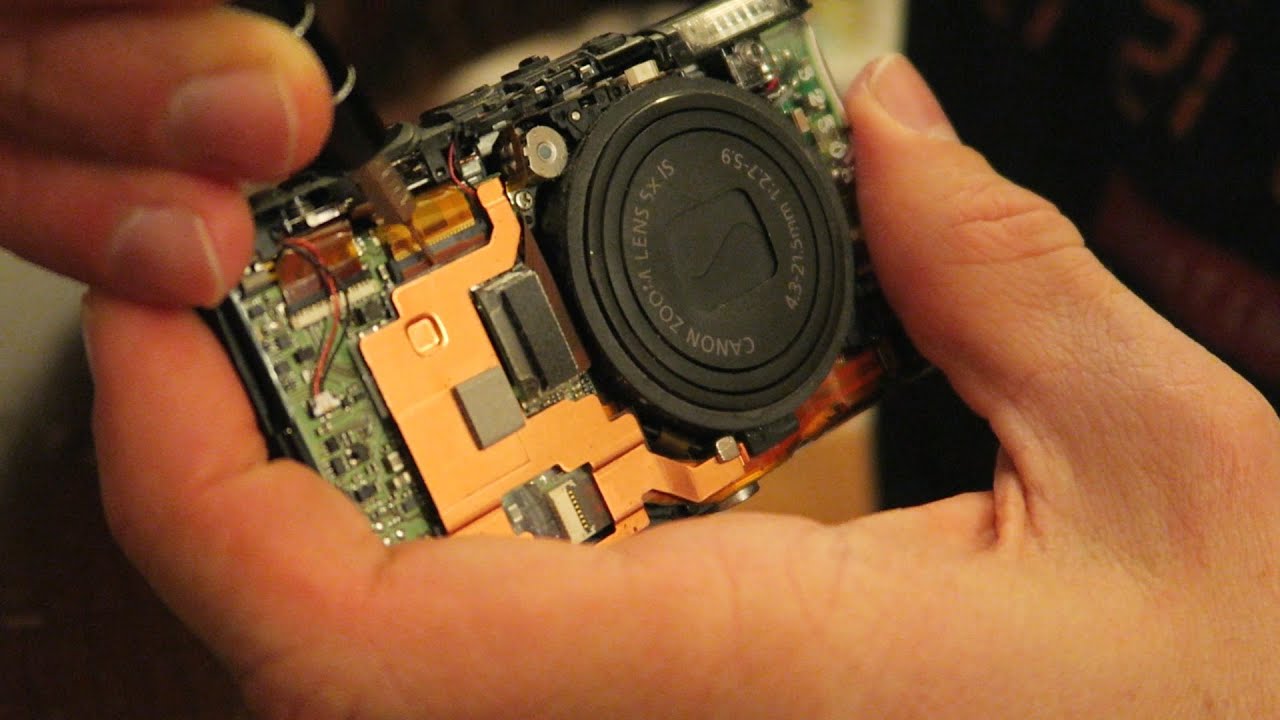
To make a digital camera, you assemble a Raspberry Pi or Arduino microcontroller, a compatible camera module, a display, and control buttons into a working enclosure, then load capture software. This build uses off-the-shelf modular components, not raw sensor fabrication, so you can focus on learning the integration and coding that bring a custom camera to life.
How to make a digital camera: what you'll build
This project produces a fully functional digital camera that captures still images and short video clips, controlled by a single-board computer. You are not manufacturing a lens from glass elements or etching a CMOS sensor; instead, you are connecting a pre-built camera module (with its integrated lens and sensor) to a microcontroller, adding a screen, buttons, and power, then writing a simple script to trigger captures. If you would rather skip the build and simply choose a point and shoot digital camera for ready-made portability, that option saves you the soldering. The result is a real camera you can hold, operate, and modify, ideal for learning embedded systems, Python programming, or building a custom time-lapse rig, wildlife trap, or inspection tool.
Materials and components you need
Gather these parts before starting; all are widely available from electronics suppliers. The exact model numbers can vary, but the function of each item is fixed.
- Compatible camera module, for Raspberry Pi: Pi Camera Module v1.3, v2, or HQ; for Arduino: OV2640, OV7670, or Arducam Mini module.
- Push buttons, at least three: shutter, menu/select, and navigation (up/down). Use tactile switches rated for 6mm or 12mm.
- Rechargeable battery or USB power bank, 5V/2A output for Raspberry Pi; 3.3V or 5V regulated for Arduino depending on logic level.
- MicroSD card (8GB or larger, Class 10), for the Raspberry Pi OS and image storage; for Arduino, a separate microSD shield/module.
- Enclosure, a 3D-printed case (STL files available online) or a generic ABS project box with cutouts.
- Basic tools, soldering iron, wire strippers, jumper wires (M-F and M-M), small screwdriver set, and a hot glue gun for securing components.
Step 1: Prepare your microcontroller and camera module
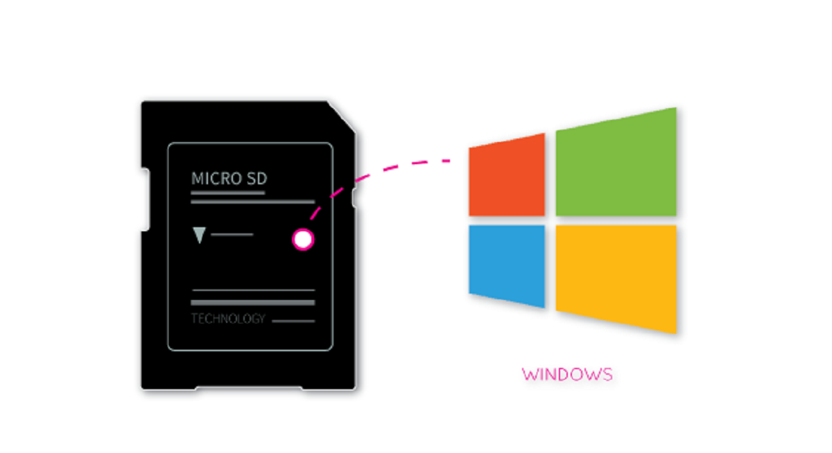
Start by installing the operating system or firmware on your board. For Raspberry Pi, flash the latest Raspberry Pi OS onto the microSD card using the Raspberry Pi Imager tool. Boot the Pi, connect to Wi-Fi or Ethernet, and run sudo apt update && sudo apt full-upgrade to ensure all packages are current.
Next, connect the camera module. On Raspberry Pi, locate the CSI (Camera Serial Interface) port on the board. Gently lift the plastic latch, insert the ribbon cable with the silver contacts facing toward the HDMI port (on most models), and press the latch down. Enable the camera in software by running sudo raspi-config, selecting "Interface Options" → "Camera" → "Enable", then reboot. Verify the camera is detected with vcgencmd get_camera; it should return supported=1 detected=1.
Refer to your specific module's pinout documentation for correct pin assignments. Solder header pins to the module, then use jumper wires to connect them to the Arduino's appropriate pins as specified in the module's documentation.
Step 2: Connect the LCD display
Mount the LCD screen in the enclosure or on a breadboard for initial testing. For a Raspberry Pi with an HDMI display, simply plug the HDMI cable into the Pi's HDMI port and power on, the desktop interface should appear automatically.
After wiring, install the display driver. On Raspberry Pi, if using a TFT, download the display's driver package (e.g., from Waveshare or Adafruit) and run the install script. If the screen remains blank, double-check the wiring orientation and that the backlight (LED pin) is connected to a power source (often 3.3V or 5V through a resistor).
Step 3: Wire the control buttons
Add physical push buttons for shutter, menu navigation, and settings. For each button, connect one leg to a GPIO pin and the other leg to ground (with the internal pull-up resistor enabled in software) or connect one leg to 3.3V and the other to GPIO with a 10kΩ pull-down resistor.
Use a breadboard or solder wires directly to the button terminals. In your Python script, use the gpiozero library's Button class to detect presses. On Arduino, assign digital pins (e.g., D2, D3, D4, D5) and use the digitalRead() function with pull-up resistors enabled via INPUT_PULLUP.
Test each button by printing its state to the serial console or terminal. The shutter button should trigger a capture event, while the navigation buttons should move a cursor on the LCD menu. Configure the software to debounce the buttons (e.g., a 50ms delay after a press) to prevent accidental double-triggers.
Step 4: Power the camera and add storage
Select a power source that provides stable voltage and enough current. For Raspberry Pi, a 5V/2.5A USB power bank or a 3.7V LiPo battery with a step-up converter (to 5V) works well. For Arduino, use a power source appropriate for your specific board model and power requirements. If using a battery, solder a JST connector to the power input of the board, or use a USB power bank with a short USB cable.
For storage, insert a microSD card into the Pi's card slot (already done in Step 1) or connect a microSD card module to the Arduino via SPI (CS pin, MOSI, MISO, SCK). Format the card using the appropriate file system for your specific board and storage requirements. On the Pi, the OS is already on the card; images will be saved to the home directory or a designated folder. On Arduino, install the appropriate SD library and follow its documentation for card formatting. Verify the card is recognized by running a simple read/write test in your code.
Step 5: Design the camera body and mount the lens
Now fit all components into an enclosure. Plan the layout: the camera module's lens must protrude through a hole in the front, the LCD screen sits in a cutout on the back, and the buttons are placed on the top or side. Use standoffs or hot glue to secure the microcontroller and display inside the case.
Mount the camera module securely behind the front aperture. For Raspberry Pi camera modules, the lens is fixed; just align the module's screw holes with the case's standoffs. For Arduino modules with a detachable lens (e.g., M12 lens on OV2640), screw the lens into the module's holder, then mount the module so the lens barrel fits through the front hole. Ensure the lens has a clear, unobstructed view, no glue or wires blocking the glass. If the case has a tripod mount, add a brass insert to the bottom for stability.
Step 6: Install the camera software
Write the capture script that ties everything together. On Raspberry Pi, use Python with the picamera library (for Pi Camera) or cv2 with OpenCV (for USB cameras). A basic script initializes the camera, sets resolution (e.g., 1280x720), and waits for the shutter button press. When pressed, it captures a JPEG to the SD card and displays a preview thumbnail on the LCD. If you're adapting a ready-made camera, you can also setup and use my vivitar action camera to understand its capture modes. Example snippet:
from picamera import PiCamera

from gpiozero import Button

from time import sleep
camera = PiCamera()
camera.resolution = (1280, 720)
shutter = Button(17)
while True:
if shutter.is_pressed:
camera.capture('/home/pi/image.jpg')
print("Captured!")
sleep(1)
For Arduino, use the ArduCAM library's ArduCAM class. Initialize the camera, set the resolution, and in the main loop check the button pin. When pressed, call myCAM.capture() to take a photo, then write the image data to the SD card using the SD library. For both platforms, add menu logic to adjust exposure, white balance, or resolution via the navigation buttons.
Step 7: Test, troubleshoot, and take your first photo
Power on the camera and observe the startup sequence. The LCD should light up and show either the Pi desktop or a live preview (if you enabled preview mode). Press the shutter button, you should hear a click or see a flash on the screen, and an image file should appear on the SD card. Review the image on the LCD or transfer it to a computer to check focus and exposure.
Common issues and fixes:
- No display, Check the display's power and SPI wiring; ensure the driver is loaded (on Pi, run
dmesg | grep spi). - Camera not detected, Re-seat the ribbon cable (on Pi) or re-check the pin connections (on Arduino). Run
vcgencmd get_cameraon Pi. - Blurry images, Adjust the lens focus ring (if adjustable) or move the camera closer/farther from the subject.
- Buttons not responding, Verify the GPIO pin numbers in your code match the actual wiring; check for loose jumper wires.
- Low battery warnings, Use a higher-capacity power bank or a battery with a higher mAh rating.
Once everything works, take a few test shots in different lighting conditions. Adjust the exposure time and ISO in your code (e.g., camera.iso = 200 on Pi) to improve image quality. Keep a log of the settings that work best for your environment, this will help you refine the camera for future use.
Related reading: How To Make A Robot: Ultimate Guide.