Introduction
Are you a tech enthusiast looking for a thrilling DIY project? If so, crafting your very own FM transmitter could be the perfect venture for you. In this comprehensive guide, we will delve into the fascinating world of FM transmitters and walk you through the step-by-step process of assembling a functional transmitter from scratch.
By embracing this project, you are not only gaining hands-on experience in electronics but also unlocking the potential to broadcast your favorite tunes or podcasts within your home or a small radius around it. The sense of accomplishment that comes with building a fully operational FM transmitter is truly unparalleled.
This guide is designed to be accessible to individuals with varying levels of technical expertise. Whether you are a seasoned electronics hobbyist or a curious beginner, the instructions provided here will equip you with the knowledge and skills needed to embark on this exciting journey. So, roll up your sleeves, gather your materials, and get ready to dive into the captivating realm of FM transmission.
Without further ado, let's begin this exhilarating DIY adventure by understanding the fundamental principles of FM transmitters and the essential components required for this project.
Understanding FM Transmitters
FM transmitters are ingenious devices that enable the wireless transmission of audio signals over short distances. FM, which stands for frequency modulation, is a popular method of broadcasting radio signals due to its high audio quality and resistance to noise interference. Understanding the basic principles behind FM transmitters is crucial for anyone venturing into the realm of electronics and broadcasting.
At the core of an FM transmitter lies the concept of frequency modulation. Unlike amplitude modulation (AM), which varies the strength of the carrier wave to encode information, FM alters the frequency of the carrier wave in response to the audio signal. This frequency variation is directly proportional to the amplitude of the audio signal, resulting in a signal that is less susceptible to amplitude variations and external disturbances.
The key components of an FM transmitter include an oscillator, a modulator, a power amplifier, and an antenna. The oscillator generates the carrier wave, which serves as the medium for transmitting the audio signal. The modulator then modifies the frequency of the carrier wave based on the input audio signal, thereby imparting the desired information onto the carrier wave. The power amplifier strengthens the modulated signal to a level suitable for transmission, while the antenna emits the signal into the surrounding space.
In the context of this DIY project, it's important to note that FM transmitters designed for personal use typically operate within a limited range to comply with regulatory restrictions. By harnessing the principles of FM transmission, you can harness the power to broadcast music, podcasts, or any audio content of your choice within a confined area, such as your home or backyard.
As you embark on the journey of crafting your own FM transmitter, keep in mind the fundamental role of frequency modulation in encoding and transmitting audio signals. This foundational understanding will serve as the bedrock for the subsequent steps involved in assembling and fine-tuning your DIY FM transmitter. With this knowledge in hand, you are well-equipped to proceed to the next phase of this exhilarating project.
Materials Needed
Embarking on the exciting endeavor of building your own FM transmitter requires a selection of essential materials and components. Before you dive into the construction process, it's crucial to gather the following items to ensure a smooth and successful assembly:
-
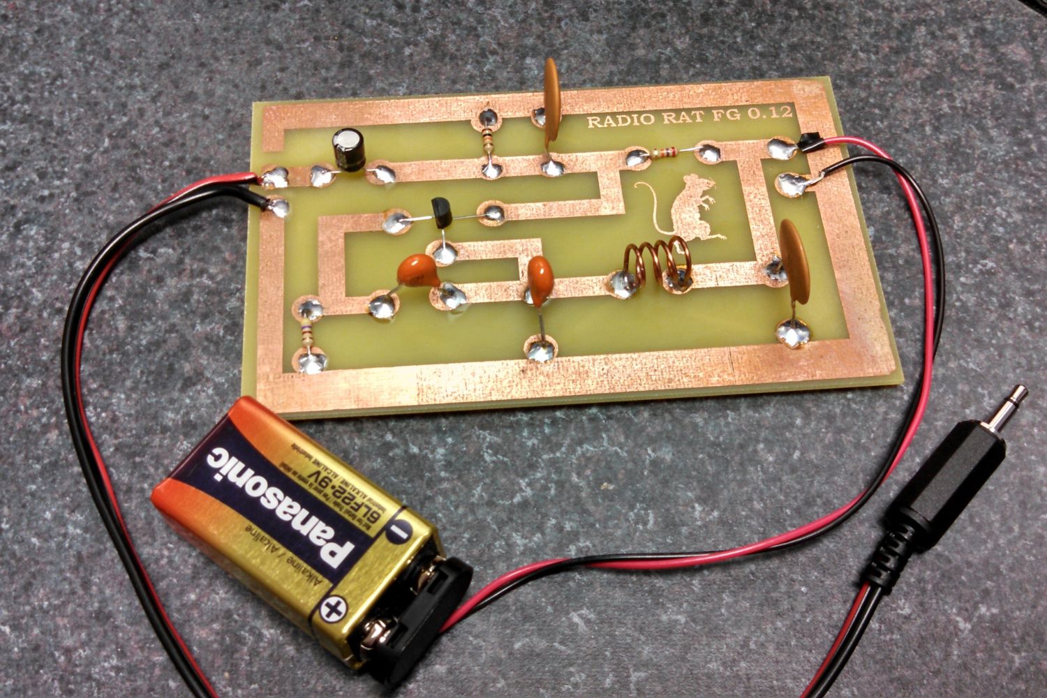
Printed Circuit Board (PCB): The foundation of your FM transmitter, the PCB serves as the platform for mounting and interconnecting various electronic components. Opt for a high-quality, single-sided PCB with copper traces to facilitate the circuitry.
-
Transistor: Select a reliable NPN transistor, such as the 2N3904, which plays a pivotal role in the amplification and modulation of the audio signal. The transistor's specifications and pin configuration are crucial factors to consider for seamless integration into the circuit.
-
Capacitors and Resistors: An assortment of capacitors and resistors is indispensable for shaping the electrical characteristics of the FM transmitter circuit. Electrolytic capacitors, ceramic capacitors, and carbon film resistors are commonly utilized in FM transmitter designs.
-
Inductor Coil: The inductor coil, often referred to as an RF choke, is instrumental in filtering and tuning the frequency of the transmitted signal. Look for a compact yet efficient inductor coil that aligns with the specifications of your FM transmitter circuit.
-
Variable Capacitor: Also known as a tuning capacitor, this component enables precise adjustment of the transmitter's frequency. A high-quality variable capacitor with smooth tuning action is essential for fine-tuning the transmission frequency to your desired range.
-
Microphone: To inject audio input into the transmitter, a small, high-sensitivity microphone is indispensable. Opt for a miniature electret condenser microphone with a built-in preamplifier for optimal audio capture.
-
Antenna: The antenna serves as the conduit for radiating the modulated FM signal into the surrounding space. A compact yet efficient antenna, such as a simple wire antenna or a telescopic antenna, is essential for effective signal propagation.
-
Power Source: Depending on the power requirements of your FM transmitter circuit, a suitable power source is essential. This may include a 9V battery, a DC power adapter, or a dedicated power supply unit capable of delivering the required voltage and current.
-
Soldering Equipment: A reliable soldering iron, solder wire, and flux are indispensable for securely connecting the electronic components to the PCB. Ensure that your soldering equipment is in optimal condition to facilitate precise and durable solder joints.
-
Enclosure (Optional): While not essential for the functionality of the FM transmitter, an enclosure provides physical protection and a professional aesthetic. Consider acquiring a suitable enclosure to house the transmitter circuitry and components.
By procuring these materials, you are laying the groundwork for a fulfilling and educational journey into the realm of FM transmission. With the essential components in hand, you are poised to proceed to the next phase of this captivating venture: assembling the circuit that will bring your DIY FM transmitter to life.
Step 1: Assembling the Circuit
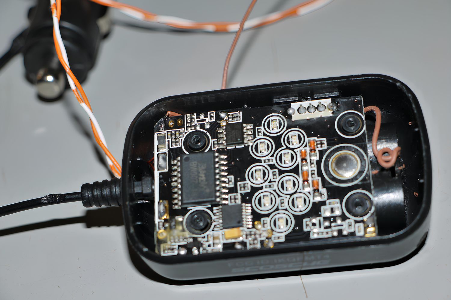
As you embark on the exhilarating journey of crafting your own FM transmitter, the foundational step involves assembling the circuit that forms the heart of the transmitter. This intricate process entails meticulously integrating the various electronic components onto the printed circuit board (PCB) to establish a functional and reliable transmitter circuit.
Begin by carefully examining the PCB to familiarize yourself with its layout and the designated areas for mounting the components. It is essential to exercise precision and attention to detail during this phase, as the proper placement and orientation of each component are critical for the seamless operation of the FM transmitter.
The first component to be integrated into the circuit is the transistor, a pivotal element responsible for amplifying and modulating the audio signal. Ensure that the transistor is securely positioned on the PCB, adhering to the specified pin configuration to facilitate seamless interconnection with the surrounding components.
Following the placement of the transistor, proceed to mount the capacitors and resistors onto their designated locations on the PCB. These components play a crucial role in shaping the electrical characteristics of the transmitter circuit, and their precise integration is paramount for achieving optimal performance.
Next, carefully incorporate the inductor coil, which serves as a vital component for filtering and tuning the frequency of the transmitted signal. Pay meticulous attention to the placement of the inductor coil to ensure its seamless integration into the circuit.
The variable capacitor, also known as the tuning capacitor, should be meticulously mounted onto the PCB, allowing for precise adjustment of the transmitter's frequency. This component enables you to fine-tune the transmission frequency to your desired range, thereby enhancing the flexibility and versatility of your DIY FM transmitter.
With these fundamental components securely integrated into the circuit, proceed to incorporate the microphone, which serves as the input source for the audio signal. Carefully connect the microphone to the designated input terminals on the PCB, ensuring a secure and reliable connection to facilitate the injection of audio input into the transmitter.
As you navigate through the intricate process of assembling the circuit, exercise patience and precision to ensure the accurate integration of each component. By methodically mounting the transistor, capacitors, resistors, inductor coil, variable capacitor, and microphone onto the PCB, you are laying the groundwork for the successful realization of your DIY FM transmitter. With the circuit taking shape, you are now poised to advance to the subsequent phase of this captivating project: connecting the antenna to facilitate the transmission of your audio signals.
Step 2: Connecting the Antenna
With the intricate circuit of your DIY FM transmitter taking shape, the next pivotal step involves the seamless integration of the antenna, a crucial component that enables the transmission of your modulated audio signals into the surrounding space. The effective connection and positioning of the antenna are paramount for optimizing the range and coverage of your FM transmission.
Begin by selecting a suitable antenna for your FM transmitter, considering factors such as size, efficiency, and compatibility with the frequency range of your transmitter. A wire antenna, often constructed from a length of insulated wire, presents a simple yet effective option for DIY FM transmitters operating within a limited range. Alternatively, a telescopic antenna, featuring adjustable segments, provides flexibility in tuning the antenna to resonate at the desired transmission frequency.
Carefully position and secure the chosen antenna to the designated terminal on the PCB, ensuring a reliable electrical connection and physical stability. The precise integration of the antenna onto the transmitter circuit is instrumental in facilitating the efficient propagation of your modulated FM signal.
Following the secure attachment of the antenna, consider the optimal positioning of the transmitter within your desired broadcasting area. Placing the transmitter at an elevated position, such as a high shelf or tabletop, can enhance the signal propagation and coverage within the intended space. Additionally, minimizing obstructions and interference around the transmitter can contribute to the clarity and reach of your broadcasted audio content.
As you connect the antenna and position the transmitter, maintain a keen focus on optimizing the transmission setup to achieve the desired coverage and signal strength. By thoughtfully integrating the antenna and strategically positioning the transmitter, you are poised to harness the full potential of your DIY FM transmitter, enabling the seamless dissemination of your favorite music, podcasts, or audio content within your chosen broadcasting environment.
With the antenna seamlessly integrated and the transmitter strategically positioned, you have successfully navigated through a pivotal phase of the DIY FM transmitter assembly process. The effective connection of the antenna sets the stage for the forthcoming step of powering the transmitter, bringing you closer to the realization of your personalized FM broadcasting system.
Step 3: Powering the Transmitter
Powering the transmitter marks a pivotal phase in the assembly process, as it involves providing the necessary electrical energy to bring your DIY FM transmitter to life. The selection of a suitable power source and the meticulous integration of the power supply components are paramount for ensuring the reliable and efficient operation of the transmitter.
Begin by identifying a power source that aligns with the voltage and current requirements of your FM transmitter circuit. Depending on the specific components and design considerations, options such as a 9V battery, a DC power adapter, or a dedicated power supply unit may be suitable for energizing the transmitter. It is essential to select a power source that not only meets the electrical specifications of the circuit but also aligns with safety standards and operational convenience.
Once the appropriate power source is identified, proceed to integrate the power supply components onto the PCB. This typically involves connecting the positive and negative terminals of the power source to the designated input points on the circuit board. Exercise precision and attention to detail during this phase to ensure secure and reliable electrical connections, thereby minimizing the risk of power-related issues during the operation of the transmitter.
Incorporate any necessary voltage regulation or filtering components to stabilize the power supply and mitigate potential electrical noise or fluctuations that could affect the performance of the transmitter. Capacitors, voltage regulators, and filtering circuits play a crucial role in maintaining a stable and clean power supply for the transmitter, contributing to the fidelity and reliability of the transmitted audio signals.
As the power supply components are seamlessly integrated into the circuit, verify the polarity and integrity of the connections to mitigate the risk of electrical shorts or malfunctions. Prioritize safety and adherence to best practices when handling and connecting the power source to the transmitter circuit, ensuring a secure and hazard-free power setup.
By effectively powering the transmitter with a reliable and appropriately matched power source, you are laying the groundwork for the successful activation and operation of your DIY FM transmitter. This pivotal phase paves the way for the forthcoming step of testing and fine-tuning the transmitter, bringing you closer to the realization of a fully functional and personalized FM broadcasting system.
Step 4: Testing and Fine-Tuning
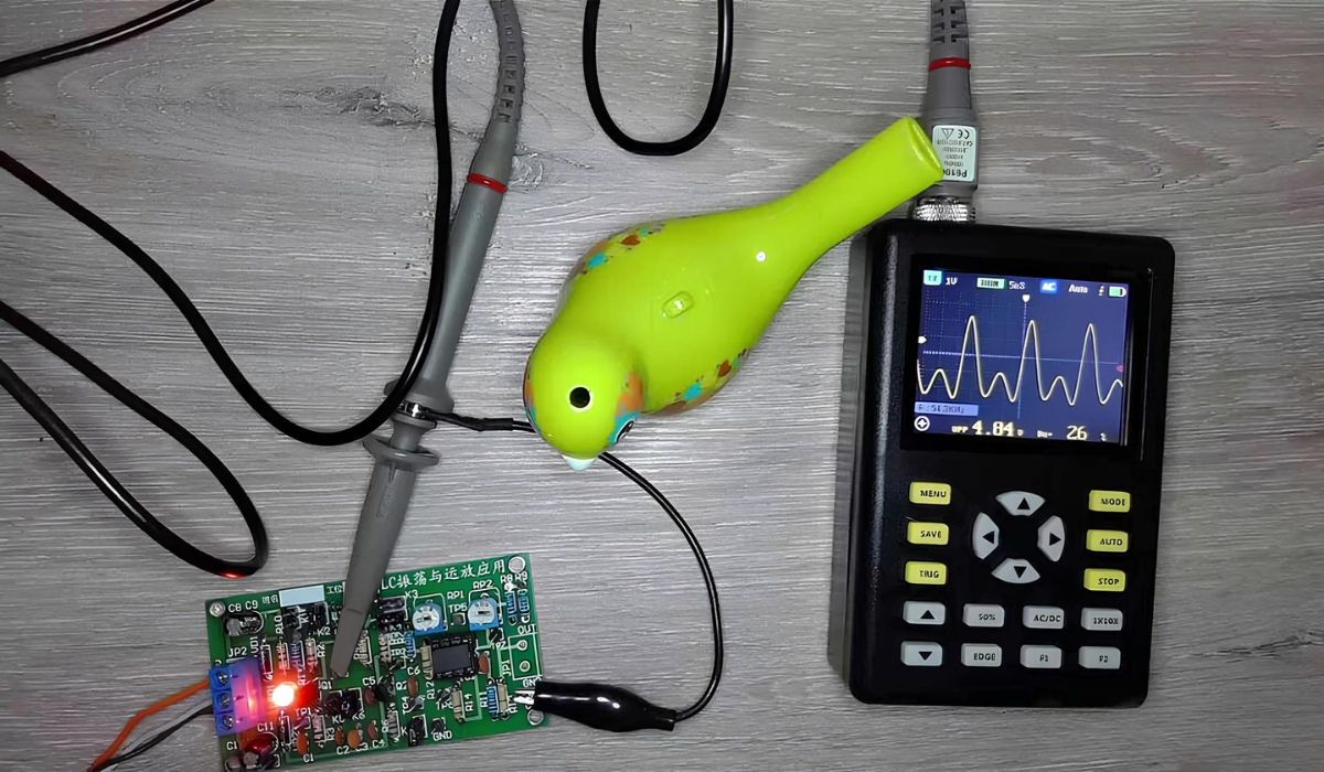
With the circuit assembled, the antenna connected, and the transmitter powered, the crucial phase of testing and fine-tuning your DIY FM transmitter commences. This pivotal step involves verifying the functionality of the transmitter, adjusting its frequency, and optimizing its performance to ensure the seamless transmission of audio signals within your desired range.
Begin by conducting an initial test to ascertain the operational status of the FM transmitter. Connect a suitable audio source, such as a music player or smartphone, to the input of the transmitter and observe the transmission of the audio signal. Listen for the broadcasted audio on an FM radio receiver within the vicinity, ensuring that the transmitted signal is clear and devoid of distortions or interference.
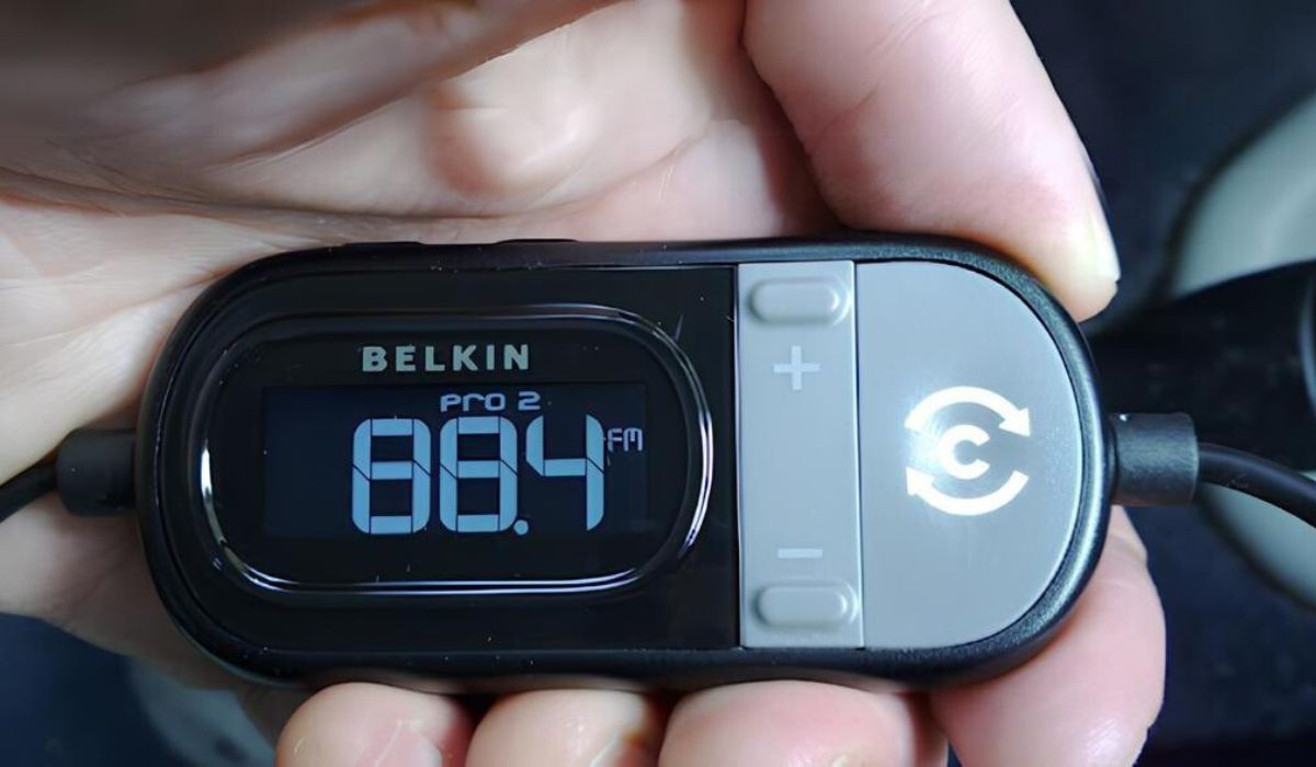
Following the initial test, proceed to fine-tune the transmission frequency to your preferred range. Utilize the variable capacitor integrated into the circuit to adjust the frequency of the transmitted signal, enabling you to align it with an open frequency on the FM band. Exercise patience and precision during this phase, as small adjustments to the variable capacitor can significantly impact the transmission frequency, allowing you to tailor the broadcasted content to your specific preferences.
As you fine-tune the transmission frequency, monitor the broadcasted audio on the FM radio receiver, ensuring that the signal remains stable and free from frequency drift. Verify that the transmitted content aligns with the intended frequency range, optimizing the clarity and fidelity of the broadcasted audio within the designated area.
Additionally, assess the coverage and range of the transmitted signal by testing the reception on FM radio receivers positioned at varying distances from the transmitter. This comprehensive evaluation enables you to gauge the effective reach of your DIY FM transmitter and make adjustments to enhance the signal strength and coverage as needed.
Throughout the testing and fine-tuning phase, maintain a meticulous approach, making incremental adjustments to the transmitter's frequency and monitoring the broadcasted audio for consistency and quality. By iteratively fine-tuning the transmitter and conducting thorough testing, you can optimize its performance and ensure the reliable dissemination of your favorite music, podcasts, or audio content within the designated broadcasting environment.
As you conclude the testing and fine-tuning phase, celebrate the successful realization of your DIY FM transmitter and revel in the fulfillment of bringing your personalized broadcasting system to life. With the transmitter operational and optimized, you have embarked on a captivating journey into the realm of FM transmission, gaining valuable hands-on experience and technical expertise along the way.
Conclusion
Congratulations on successfully navigating the exhilarating journey of crafting your very own FM transmitter! Through the meticulous assembly of the circuit, the seamless integration of the antenna, the precise powering of the transmitter, and the thorough testing and fine-tuning process, you have embarked on a captivating DIY adventure that has culminated in the realization of a personalized FM broadcasting system.
As you reflect on the multifaceted process of building your DIY FM transmitter, it's essential to acknowledge the invaluable knowledge and skills you have acquired along the way. From understanding the fundamental principles of frequency modulation to meticulously integrating electronic components onto the printed circuit board, each phase of this project has contributed to your growth as an electronics enthusiast and a hands-on creator.
Beyond the technical aspects, the journey of building a DIY FM transmitter embodies the spirit of exploration, creativity, and resourcefulness. By embracing this project, you have ventured into the realm of wireless communication and broadcasting, gaining insights into the intricacies of audio transmission and the engineering principles that underpin modern communication systems.
Moreover, the completion of your DIY FM transmitter marks the empowerment of personal expression and creativity. Whether you intend to broadcast your favorite music, share engaging podcasts, or communicate audio content within your chosen environment, the transmitter you have crafted embodies the potential for personalized communication and expression.
As you revel in the satisfaction of bringing your DIY FM transmitter to life, consider the broader implications of this endeavor. The skills and insights you have gained can serve as a springboard for further exploration in the realms of electronics, telecommunications, and hands-on innovation. Additionally, the sense of accomplishment and fulfillment derived from completing this project reinforces the value of perseverance, attention to detail, and the joy of creating something truly unique.
In conclusion, the journey of crafting your own FM transmitter transcends the mere assembly of electronic components; it embodies a spirit of curiosity, ingenuity, and the pursuit of knowledge. By channeling your passion for technology and embracing the intricacies of FM transmission, you have unlocked the potential to communicate, express, and innovate in a manner that is uniquely your own.
As you embark on future endeavors, may the experience of building your DIY FM transmitter serve as a testament to the power of hands-on exploration and the unyielding spirit of innovation. Embrace the knowledge gained, cherish the memories created, and continue to pursue new horizons in the ever-evolving landscape of technology and creativity.


