Introduction
Welcome to the world of PC cases, where small buttons can have a big impact. The power switch on a PC case is a seemingly simple component that plays a crucial role in turning your computer on and off. However, understanding the distinction between positive and negative power switch cases can be a bit confusing for beginners.
In this guide, we will unravel the mystery behind positive and negative power switch PC cases. We will explore what each type means, how to identify them, and provide a step-by-step guide to testing your power switch.
Whether you are a DIY enthusiast building your own computer or a technician troubleshooting power-related issues, knowing how to differentiate between positive and negative power switch PC cases is essential. Let’s dive in and demystify the world of power switches.
But first, let’s briefly discuss the significance of power switches in PC cases. The power switch is essentially a button located on the front panel of your computer case that allows you to turn your computer on or off with a simple press. It serves as a bridge between the motherboard and the power supply unit (PSU), allowing them to communicate and control the flow of electricity.
Now that we understand the importance of power switches, it’s time to explore the difference between positive and negative power switch PC cases. By understanding the distinction, you’ll be better equipped to troubleshoot and connect your power switch correctly.
Understanding Power Switch PC Case
Before we delve into the specifics of positive and negative power switch PC cases, let’s have a brief overview of how they function and why they are important.
The power switch on a PC case acts as a trigger for the motherboard to start or stop the power supply. When you press the power switch, it sends a signal to the motherboard, which in turn instructs the power supply unit (PSU) to provide power to the different components of your computer. Conversely, when you press the power switch again, it signals the motherboard to shut down the system properly.
A power switch has two connectors: one for the positive terminal (+) and one for the negative terminal (-). Understanding the polarity of the power switch is crucial in ensuring that it functions correctly when connected to the motherboard.
It’s important to note that power switch designations can vary between manufacturers and case models. However, the concept of positive and negative remains universally applicable, regardless of the labeling or color coding on the connectors or cables.
Positive power switch cases are designed with a positive (+) sign or a label indicating “P” near the positive connector. On the other hand, negative power switch cases might feature a negative (-) sign or a label “N” near the negative connector.
The polarity of the power switch determines the direction of the electrical current flow through the switch. Connecting the power switch with the correct polarity ensures that the signal is properly transmitted to the motherboard and the system functions as intended.
Now that we have a basic understanding of power switch PC cases, let’s explore the characteristics of positive and negative power switches in more detail.
Positive Power Switch PC Case
A positive power switch PC case is designed to have a positive terminal or connector (+) on its power switch. This means that the power switch sends the signal to the motherboard when the positive terminal is connected correctly.
Positive power switch cases are often marked with a plus sign (+) or labeled “P” near the positive connector. The positive terminal is typically connected to the power switch button, while the negative terminal is connected to the ground or common pin on the motherboard.
When the power switch is pressed in a positive power switch case, the electrical current flows from the positive terminal through the switch and into the motherboard’s ground pin. This completes the circuit and signals the motherboard to initiate the start-up process.
Positive power switch cases are more commonly found in traditional desktop PC cases and are widely supported by motherboards. If you are unsure whether your case has a positive power switch, refer to the manufacturer’s documentation or look for any markings near the connectors.
It’s important to connect the positive terminal of the power switch to the corresponding positive header pin on the motherboard. Failing to do so may result in the power switch not functioning correctly, leading to issues with powering on or off your computer.
Now that we understand the characteristics of positive power switch cases, let’s move on to the next section to explore negative power switch cases and how they differ.
Negative Power Switch PC Case
A negative power switch PC case is defined by having a negative terminal or connector (-) on its power switch. In this case, the power switch sends the signal to the motherboard when the negative terminal is connected correctly.
Negative power switch cases are often labeled with a minus sign (-) or marked with an “N” near the negative connector. The negative terminal is typically connected to the power switch button, while the positive terminal is connected to the motherboard’s ground or common pin.
When the power switch is pressed in a negative power switch case, the electrical current flows from the negative terminal through the switch and into the motherboard’s positive or ground pin. This completes the circuit and triggers the motherboard to initiate the start-up process.
Negative power switch cases are less common than positive power switch cases but can still be found in both old and newer PC case models. To determine if your case has a negative power switch, check the manufacturer’s documentation or look for any markings near the connectors.
Just like with positive power switch cases, it’s crucial to ensure that the negative terminal of a power switch is connected to the corresponding negative header pin on the motherboard. Properly connecting the power switch is essential for it to function correctly and avoid any issues with powering on or off the computer.
Now that we have explored the characteristics of negative power switch cases, let’s move on to the next section to understand how to identify whether your PC case has a positive or negative power switch.
How to Identify Positive/Negative Power Switch PC Case
Identifying whether your PC case has a positive or negative power switch is crucial to ensure proper connection and functionality. Here are a few methods to help you determine the polarity of your power switch:
1. Check the Case or Switch Labeling: Look for any markings or labels near the power switch connectors on your PC case. Positive power switch cases may feature a plus sign (+) or “P” label, while negative power switch cases might have a minus sign (-) or “N” label. These labels indicate the polarity of the connectors.
2. Review the Case Manual or Specifications: Consult the manufacturer’s documentation or the specifications of your PC case. They often provide information about the polarity of the power switch connectors. The manual may also include diagrams or illustrations that clearly indicate which connector is positive and which is negative.
3. Observe Wire Color Coding: In some cases, the wires connected to the power switch may be color-coded. While this is not always the case, it can provide a clue about the polarity. For example, red wires are commonly associated with positive connections, while black or white wires are often used for negative connections. However, it’s important to note that wire colors can vary, so it’s best to cross-reference this information with other methods.
4. Use a Multimeter: If you have a multimeter, you can use it to test the power switch connectors’ polarity. Set the multimeter to the continuity or resistance mode and touch the probes to the power switch terminals. If the multimeter reads a positive value, it indicates that the terminal is positive. Conversely, if the multimeter reads a negative value or no value, it indicates that the terminal is negative.
Remember, the goal is to identify whether your power switch case is positive or negative. Once you have determined the polarity, you can proceed with connecting the power switch to the motherboard accordingly.
Now that you know how to identify the polarity of your power switch case, the next section will provide a step-by-step guide on how to test the power switch to ensure it is functioning correctly.
Step-by-Step Guide: Testing the Power Switch
Testing the power switch is an important step to ensure it functions correctly before connecting it to your motherboard. Follow these step-by-step instructions to test the power switch:
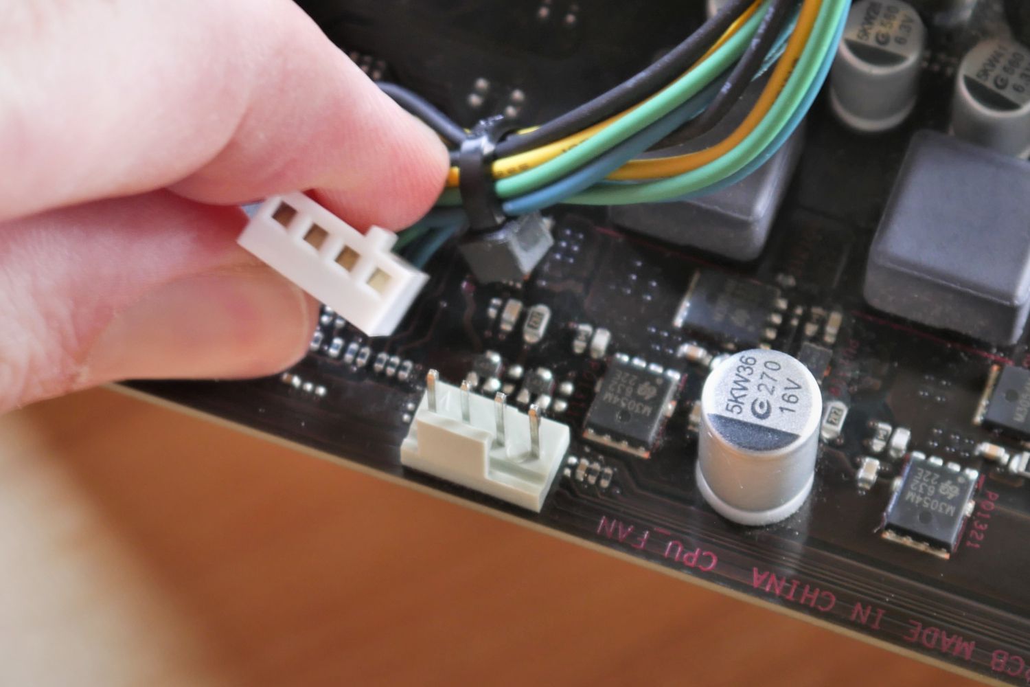
Step 1: Disconnect the Power Switch: Start by disconnecting the power switch from the motherboard. This prevents any accidental power-on or power-off events while testing.
Step 2: Inspect the Power Switch: Take a close look at the power switch and its connectors. Check for any visible damage or loose wires that might affect its functionality. If you notice any issues, consider replacing the power switch with a new one.
Step 3: Set Up the Testing: Prepare a multimeter or continuity tester to test the power switch. Set the multimeter to the continuity or resistance mode, depending on the options available on your device.
Step 4: Test the Power Switch: Connect the positive and negative probes of the multimeter to the corresponding power switch terminals. Press the power switch button while observing the multimeter. If the multimeter shows continuity or a change in resistance value, it indicates that the power switch is functioning correctly.
Step 5: Check for Consistent Results: Repeat the test multiple times to ensure consistent results. If the power switch consistently shows continuity or resistance changes when pressed, it indicates that it is working properly.
Step 6: Consider Replacing the Power Switch: If the power switch does not show any continuity or resistance changes when tested, or if the values are inconsistent, it may be faulty. In this case, it’s recommended to replace the power switch with a new one to avoid any issues with powering on or off your computer.
Step 7: Connect the Power Switch to the Motherboard: Once you have confirmed that the power switch is working correctly, connect it to the corresponding header pins on the motherboard, ensuring you maintain the correct polarity.
By following these steps and testing the power switch prior to connecting it to the motherboard, you can ensure a smooth and trouble-free operation of your computer’s power button.
Now that you have successfully tested the power switch, it’s time to conclude our guide and apply this knowledge to your own PC case and motherboard setup.
Conclusion
Understanding the difference between positive and negative power switch PC cases is crucial for anyone working with computers, whether you’re building your own system or troubleshooting power-related issues. By correctly identifying and connecting the power switch, you can ensure seamless functionality and prevent any issues with powering on or off your computer.
In this guide, we explored the significance of power switches in PC cases and how they act as the bridge between the motherboard and the power supply unit (PSU). We learned that positive power switch PC cases have a positive (+) terminal, while negative power switch PC cases have a negative (-) terminal.
We also provided helpful methods to identify whether your PC case has a positive or negative power switch, such as checking labeling or color coding, reviewing the case manual or specifications, and utilizing a multimeter to test for polarity.
Additionally, we offered a step-by-step guide for testing the power switch to ensure its proper functionality before connecting it to the motherboard. By following these steps, you can verify the power switch’s continuity or resistance and determine if it needs replacement.
Remember, always consult the manufacturer’s documentation or seek professional assistance if you’re uncertain about the polarity or connection of your power switch. Incorrectly connecting the power switch can lead to system malfunctions or damage.
With this knowledge and understanding, you are now equipped to confidently identify, test, and connect the power switch in your PC case. By paying attention to the polarity and following the correct procedures, you’ll maintain smooth operation and have the power to control your computer at your fingertips.
Happy computing!